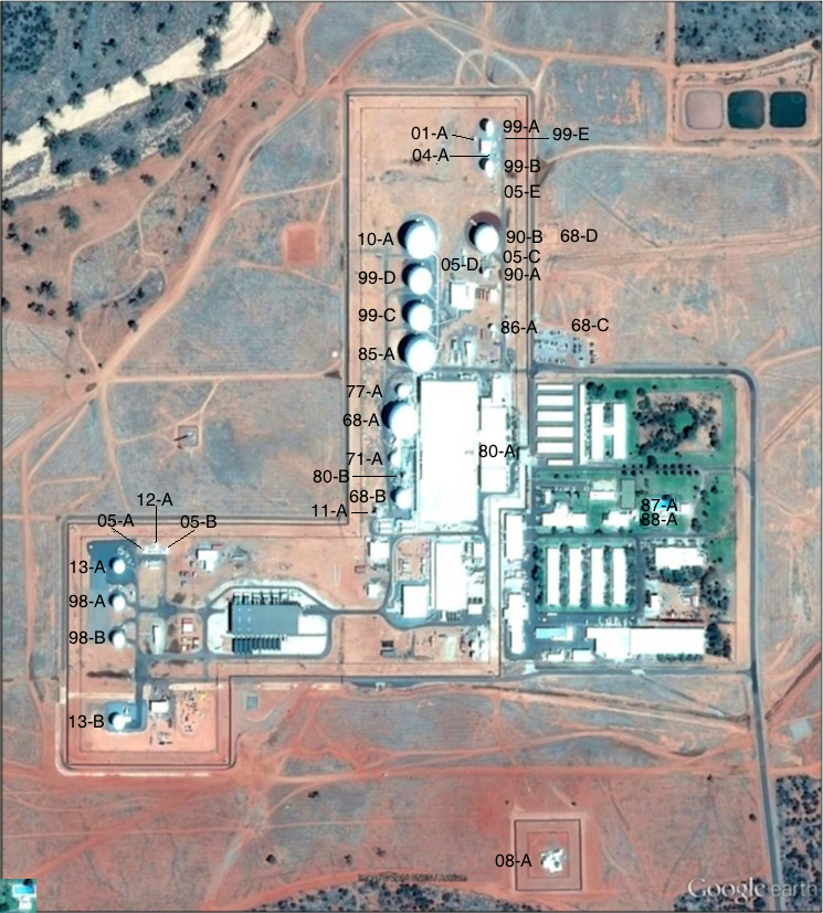
Figure 1. Antenna systems at Pine Gap, Google Earth imagery, 6 November 2015.
Note: for antenna identification system see Desmond Ball, Bill Robinson and Richard Tanter, The Antennas of Pine Gap, Nautilus Institute, Special Reports, February 2016.
Antenna identification system
One aim of this research is to identify all antenna systems installed at Pine Gap since 1967, with a view to then understand their characteristics and likely roles. There is no publicly available information about the system by which the US government identifies antennas and other elements of Pine Gap infrastructure. Over a number of years, the authors have used different systems of antenna identification, each mainly based on the numerical order in which antennas were installed. As the number of antennas known to have been installed grew, and as more accurate information about the date of antenna installation was established (and on occasion revised more than once), it became clear that the identification of a particular antenna in a straightforward chronological system may need to be revised, sometimes more than once, leading to confusion. In Table 1, column 2, the authors introduce a year-based identification system.
The antennas are listed in chronological order, with some allowance for uncertainty in particular cases. The antenna identification number in column 2 is based on the year that the antenna was installed (see column 6), with a letter suffix further identifying it within the group installed that year. The first antenna listed, 67-A, was built in 1967, and it was the first (and only) antenna built that year. The second antenna listed, 68-A, was one of four installed in the following year. In cases of uncertainty, the best estimate is noted with a question mark. When an antennna is known to have been installed at some point during a specific period, the indentification number is derived from the earliest possible year of construction in that range – e.g. antenna 86-A is known to have been installed between 1986 and 1988.
Table 1. Antennas at Pine Gap
(Source: Desmond Ball, Bill Robinson, and Richard Tanter, The Antennas of Pine Gap, Nautilus Institute Special Report, 22 February 2016.)
|
Authors’
|
Size (ft.) antenna/
|
Size (m.) antenna/
|
Coordinates |
Built |
Comments |
|
| 1 | 67-A | ? | 1967 | No radome. UHF Yagi antenna.Located on the roof of the Operations Building. Provided link to the Alice Springs Telecom tower.Dismantled. |
||
| 2 | 68-A | 85/125 | 26/38 | -23.798403°,
133.736261° |
1968 | Radome replaced in 1977. |
| 3 | 68-B | ?/67 | ?/20 | -23.799296°,
133.736276° |
1968 | Radome replaced in 1977. |
| 4 | 68-C | ? | -23.797437°,
133.738290° |
1968 | No radome.
HF radio transmitting antenna. |
|
| 5 | 68-D | ? | -23.796319°,
133.738033° |
1968 | No radome.
HF radio receiving antenna. Tower is about 15 metres high. |
|
| 6 | 69-A | ?/60 | ?/18 | -23.798040°,
133.737430° |
1969 | Radome.
‘Research’ dish. Dismantled in 1973. Site occupied by 73-A in 1973. |
| 7 | 69-B | ?/15 | ?/5 | -23.798814°,
133.736224° |
1969 | Radome.
Dismantled in 1980. Upgraded to 80-B in 1980. |
| 8 | 69-C | ? | ? | ? | 1969 | No radome.
Dismantled. |
| 9 | 71-A | ?/50 | ?/15 | -23.798849°,
133.736185° |
1971 | Radome. |
| 10 | 73-A | 35/60 | 11/18 | -23.798040°,
133.737430° |
1973 | Radome.
SCT-35 DSCS dish. Dismantled in 1991-1994. Located at site previously occupied by 69-A. Operations Building addition built on site c.1998. |
| 11 | 77-A | ?/50 | ?/15 | -23.798071°,
133.736247° |
1977 | Radome. |
| 12 | 80-A | 8/15 | 2/5 | -23.798773°,
133.737046° |
1980 | Radome.
SCT-8 DSCS dish. Installed on roof of Operations Building. |
| 13 | 80-B | ?/25 | ?/8 | -23.799051°,
133.736280° |
1980 | Radome.
‘Upgrade’ in size of 69-B. |
| 14 | 84-A | ? | ? | ? | 1984 | No radome. Large HF LPA.Dismantled by 1997. |
| 15 | 85-A | 95-100/125 | 29-31/38 | -23.797614°,
133.736466° |
1985 | Radome. Reportedly associated with the Orion-1 (Magnum-1) satellite. |
| 16 | 86-A | 25/ | 8/ | -23.797372°,
133.737366° |
1986-1988 | No radome. |
| 17 | 87-A | 18/ | 5/ | -23.799438°,
133.739077° |
1986-1988 | No radome.
South of tennis court. TV reception? |
| 18 | 88-A | 18/ | 5/ | -23.799505°,
133.739129° |
1986-1988 | No radome.
South of tennis court. TV reception? |
| 19 | 88-B | ? | ? | 1986-1988 | No radome. Dismantled. |
|
| 20 | 89-A | ?/22 | ?/7 | -23.799415°,
133.735998° |
1989 | Radome.
Dismantled. Site later occupied by 11-A. |
| 21 | 90-A | ?/30 | ?/9 | -23.796753°,
133.737278° |
1990-1991 | Radome.
One of pair announced in August 1990. Communications. |
| 22 | 90-B | ?/100 | ?/30 | -23.796316°,
133.737278° |
1990-1991 | Radome.
One of pair announced in August 1990. Communications. |
| 23 | 98-A | 33/52 | 10/16 | -23.800425°,
33.732769° |
1998 | Radome. DSP/SBIRS. |
| 24 | 98-B | 33/52 | 10/16 | -23.800811°,
133.732769° |
1998 | Radome. DSP/SBIRS. |
| 25 | 99-A | 66/ | 20/ | -23.795116°,
133.737281° |
1999? | No radome.
Communications re DSP/SBIRS. |
| 26 | 99-B | 66/ | 20/ | -23.795576°,
133.737288° |
1999? | No radome.
Communications re DSP/SBIRS. |
| 27 | 99-C | 72/100 | 22/30.5 | -23.797218°,
133.736466° |
1999 | Radome.
One of pair built just N of 85-A. FORNSAT/COMSAT collection role. |
| 28 | 99-D | 72/100 | 22/30.5 | -23.796774°,
133.736462° |
1999 | Radome.
One of pair built just N of 85-A. |
| 29 | 99-E | 3/ | -23.795257°,
133.737448° |
Before 9.2004 | No radome.
Present in 1999 DoD photo. |
|
| 30 | 01-A | 6/ | -23.795250°,
133.737121° |
Before 9.2004 | No radome. | |
| 31 | 01-B | 2.5/ | -23.795135°,
133.736749° |
Before 9.2004 | No radome.
Present ?/2004-2012/13. Dismantled in 2013. |
|
| 32 | 01-C[1] | No radome.
Dismantled. Not present in September 2004. |
||||
| 33 | 03-A | 16/ | 5/ | -23.799829°,
133.732699° |
2003-2004? | No radome.
RGS area. Dismantled in 2011-2012. |
| 34 | 03-B | 16/ | 5/ | -23.800025°,
133.732712° |
2003-2004? | No radome.
RGS area. Dismantled in 2011-2012. |
| 35 | 04-A | western mast:
-23.795454°, 133.737057°
eastern mast: -23.795459°, 133.737176° |
8.2005 – 10.2009 | Helical antenna array.
Located on southwest and southeast corners of the building between 99-A and 99-B. Two small single helical antennas installed by September 2004. Present in Google Earth imagery dated 8 September 2004. |
||
| 36 | 05-A | ?/17 | ?/5 | -23.799853°,
133.733103° |
2005-2008? | Radome.
STSS-related? |
| 37 | 05-B | ?/17 | ?/5 | -23.799856°,
133.733361° |
2005-2008? | Radome.
STSS-related? |
| 38 | 05-C | 4/ | -23.796584°,
133.737283° |
2005-2009 | No radome.
Built in 2005-2009. |
|
| 39 | 05-D | 4/ | -23.796594°,
133.737190° |
2005-2009 | No radome.
Built in 2005-2009. |
|
| 40 | 05-E
|
-23.795813°, 133.737426° |
2005-2009 | Helical antenna array.
Located south of 99-B. Four masts with twin helicals installed between 2005 and 2009. Not present in Google Earth imagery dated 11 August 2005. Present in TerraServer imagery in October 2009. |
||
| 41 | 08-A | 75?/ | 23?/ | -23.803366°,
133.738043° |
2008 | Torus multiple-beam antenna.
FORNSAT/COMSAT collection role. |
| 42 | 10-A | 95-100?/125 | 29-31?/38 | -23.796265°,
133.736433° |
2010
|
Radome. Probably associated with the Orion-7 satellite. |
| 43 | 11-A | 40/ | 12/ | -23.799440°,
133.735973° |
2011-2012 | No radome.
Installed on the site previously occupied by 89-A. |
| 44 | 12-A | ?/17 | ?/5 | -23.799822°,
133.733232° |
2012 | Radome.
STSS-related? |
| 45 | 13-A | 33?/52? | 10/16 | -23.800003°,
133.732771° |
2013 | Radome.
DSP/SBIRS. |
| 46 | 13-B | ?/ca. 60? | ?/18 | -23.801743°,
133.732762° |
2013 | Radome.
SBIRS-related? |
[1] The existence of Antenna 01-C is implied in the May 2002 Ministerial Statement that three uncovered antennas were installed between the 1999 official photograph (Figure 31) and May 2002.
Project coordinator: Richard Tanter
Updated: 22 February 2016
Simply great compiled information and extremely helpful with my close interest in this and other defense facilities. Thank you for all your efforts in this, and all endeavors concerning national security. RMR