")
This gallery holds links to all images reproduced in Desmond Ball, Bill Robinson and Richard Tanter, The Antennas of Pine Gap, Nautilus Institute, Special Reports, 18 February 2016.
Cover – high resolution image.
Details of the antennas are listed in Table 1 in that paper.
The antennas identification system in Table 1 and in the images below is a year-based identification system.
The antennas are listed in chronological order, with some allowance for uncertainty in particular cases. The antenna identification number in column 2 is based on the year that the antenna was installed (see column 6), with a letter suffix further identifying it within the group installed that year. The first antenna listed, 67-A, was built in 1967, and it was the first (and only) antenna built that year. The second antenna listed, 68-A, was one of four installed in the following year. In cases of uncertainty, the best estimate is noted with a question mark. When an antenna is known to have been installed at some point during a specific period, the identification number is derived from the earliest possible year of construction in that range – e.g. antenna 86-A is known to have been installed between 1986 and 1988.
We are deeply grateful to Felicity Ruby and Kristian Laemmle-Ruff, who very generously gave us permission to reproduce their photographs of Pine Gap.
NOTE ON ATTRIBUTION
Images in this paper by Kristian Laemmle-Ruff and by Felicity Ruby may be used for non-commercial purposes, subject to attribution and other conditions under Creative Commons Licence Attribution 2.0 Generic (CC BY 2.0): see http://creativecommons.org/licenses/by/2.0/.
See Kristian Laemmle-Ruff Photography, and Felicity Ruby – The Fourth Eye.
The source images by Kristian Laemmle Ruff used for Figures 4, 9, 30, 32, 37, 39, 46, 47, 49, 55 and the cover image are available here in medium-level resolution.
Very large file size versions of Laemmle-Ruff’s images are available through his website.
Media requests for reproduction rights should be directed to that website.
Felicity Ruby’s photographs are available here and through her website.
Click on thumbnails for fullsize image
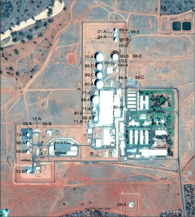 Figure 1. Antenna systems at Pine Gap, Google Earth imagery, 6 November 2015. |
 Figure 2. |
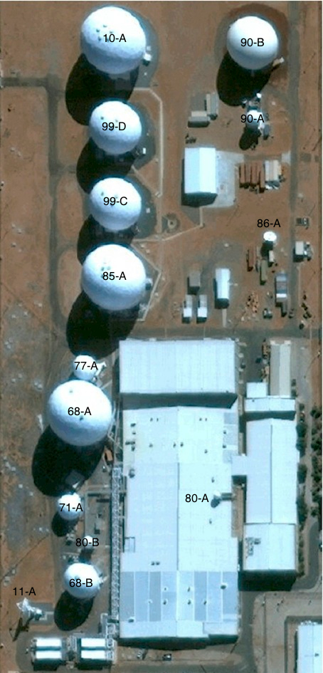 Figure 3. Pine Gap signals intelligence compound, 2012 – annotated |
 Figure 4. |
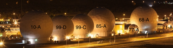 Figure 4. Principal SIGINT and FORNSAT/COMSAT parabolic antennas in radomes |
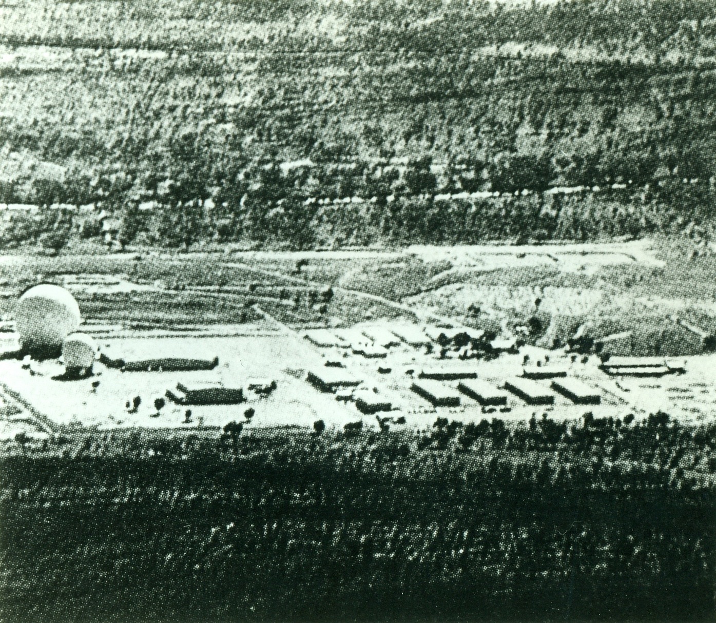 Figure 5. Two radomes at Pine Gap, 1968-69 (Antennas 68-A and 68-B) |
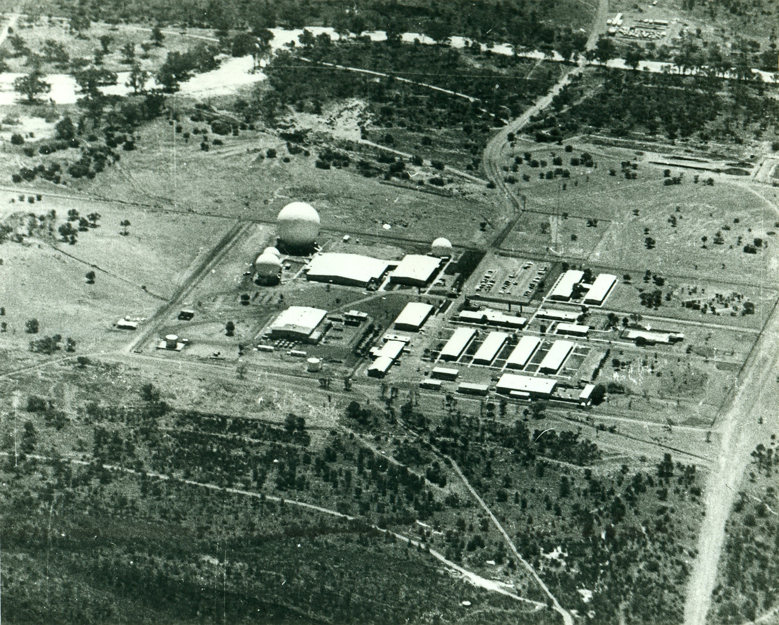 Figure 6. Five radomes at Pine Gap, 1973-77 (Antennas 68-B, 71-A, 68-A and 73-A; 69-B not visible – collimation tower to left of 68-A) |
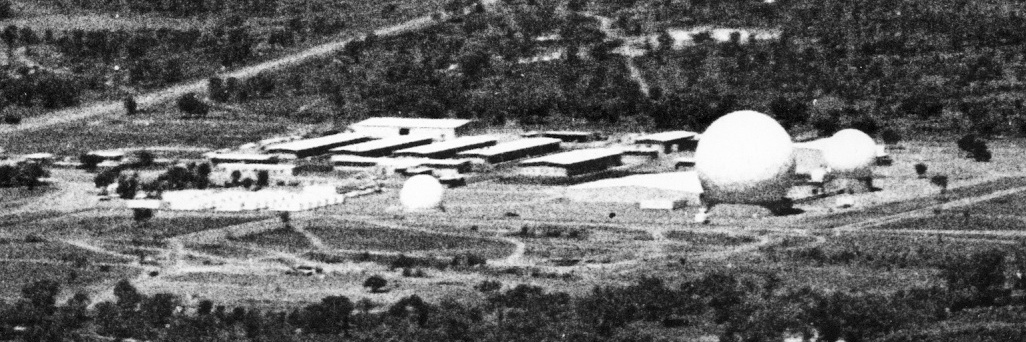 Figure 7. Four radomes at Pine Gap, 1969-71 (Antennas 69-A, 68-A, 69-B and 68-B) |
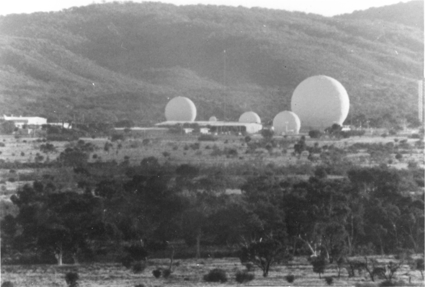 Figure 8. Five radomes at Pine Gap, 1971-77 (68-A, 73-A, 71-A, 69-B and 68-B) |
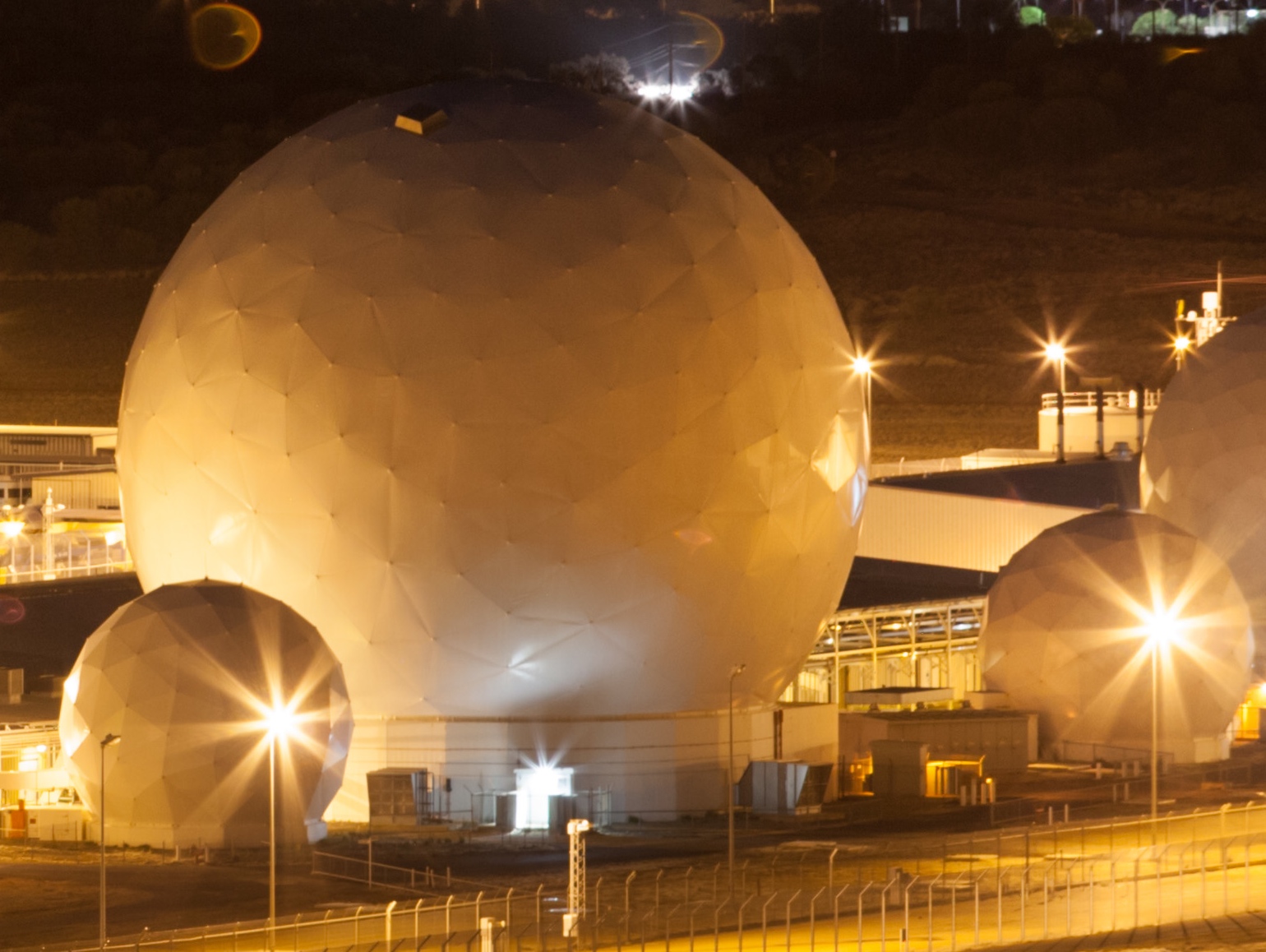 Figure 9. Antennas 77-A, 68-A, 71-A, 68-B |
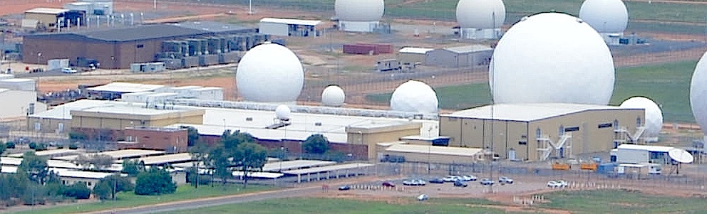 Figure 10. Antennas 68-B, 80-A (on Operations Building roof), 80-B, 71-A, 68-C (HF transmitter), 68-B, 77-A and 86-A, 23 January 2016 |
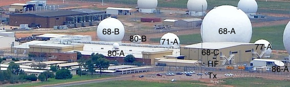 Figure 10. (annotated) Antennas 68-B, 80-A (on Operations Building roof), 80-B, 71-A, 68-C (HF transmitter), 68-B, 77-A and 86-A, 23 January 2016 |
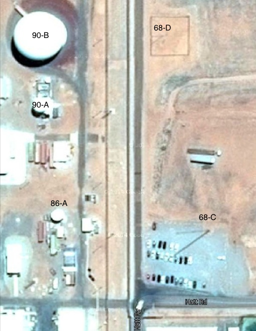 Figure 11. HF transmitter (68-C) and receiver (68-D) antennas at Pine Gap, |
 Figure 12. Ford Aerospace SCT-35 DSCS antenna system. |
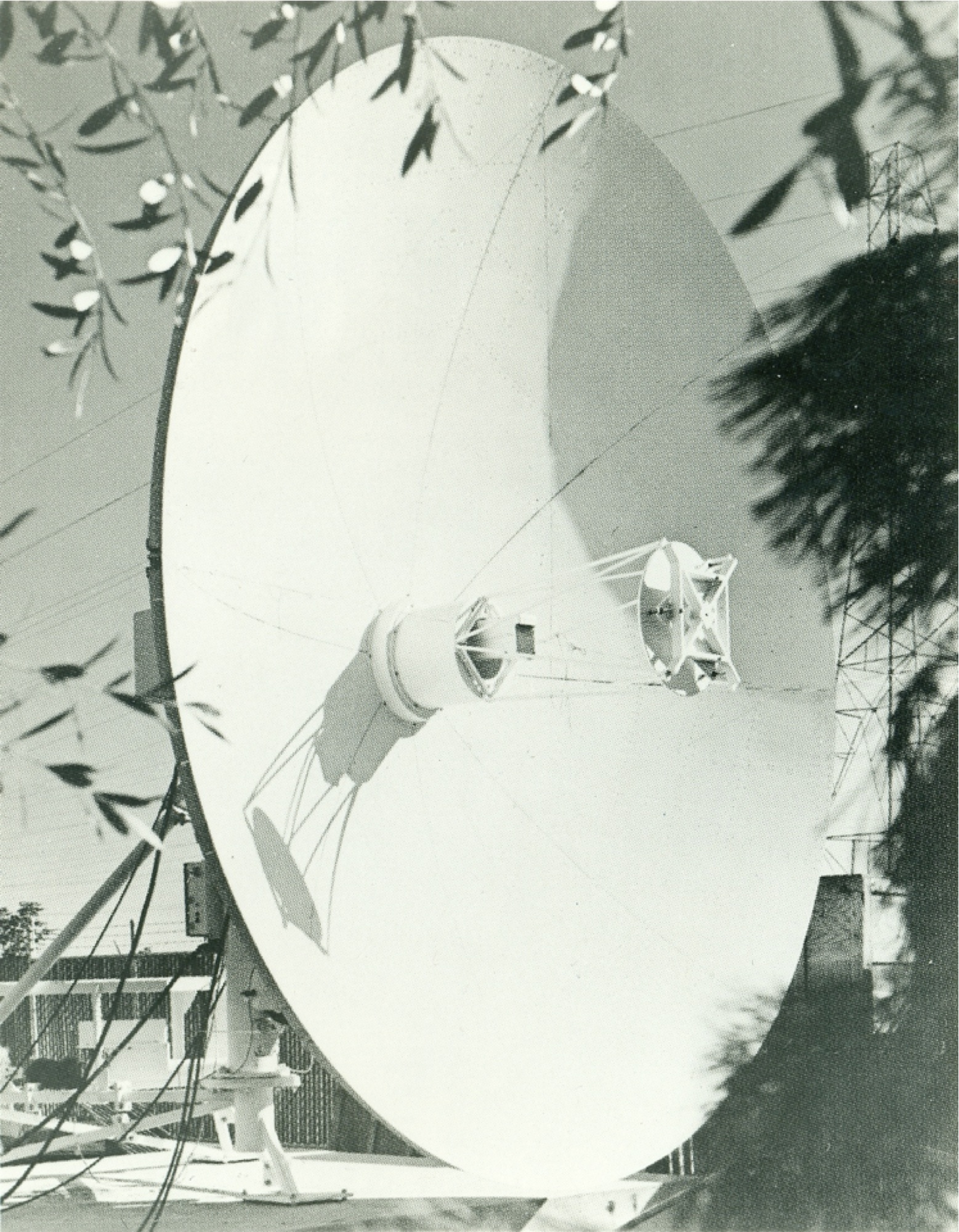 Figure 13. Ford Aerospace SCT-8 DSCS antenna system. |
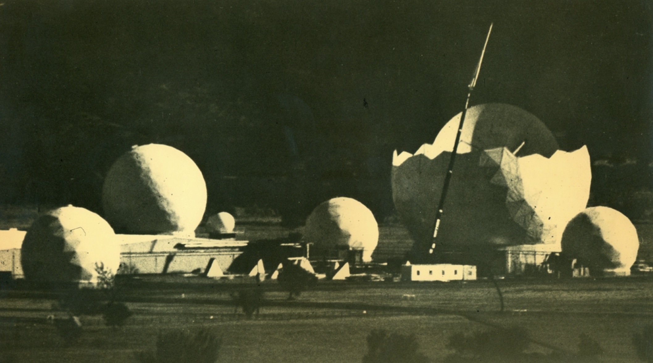 Figure 14. Six radomes, 1977 (Antennas 73-A, 68-B, 69-B, 71-A, 68-A and 77-A) |
![Figure 15. Six radomes, 1977 (Antennas 68-C [HF], 73-A, 68-B, 69-B, 71-A, 68-A and 77-A)](https://nautilus.org/wp-content/uploads/2016/02/Figure-15.-Six-radomes-1977-Antennas-68-C-HF-73-A-68-B-69-B-71-A-68-A-and-77-A.jpg) Figure 15. Six radomes, 1977 (Antennas 68-C [HF], 73-A, 68-B, 69-B, 71-A, 68-A and 77-A) |
![Figure 16. Seven radomes at Pine Gap, 1983 (Antennas 73-A, 77-A, 80-A [on the roof of the Operations Building], 68-A, 71-A, 80-B and 68-B). Source: ‘Concern Rises Over “Spy Role”’, Centralian Advocate, 18 January 1985, (photograph taken January-July 1983).](https://nautilus.org/wp-content/uploads/2016/02/Figure-16.-Seven-radomes-at-Pine-Gap-1983-Antennas-73-A-77-A-80-A-on-the-roof-of-the-Operations-Building-68-A-71-A-80-B-and-68-B.jpg) Figure 16. Seven radomes at Pine Gap, 1983 (Antennas 73-A, 77-A, 80-A [on the roof of the Operations Building], 68-A, 71-A, 80-B and 68-B). |
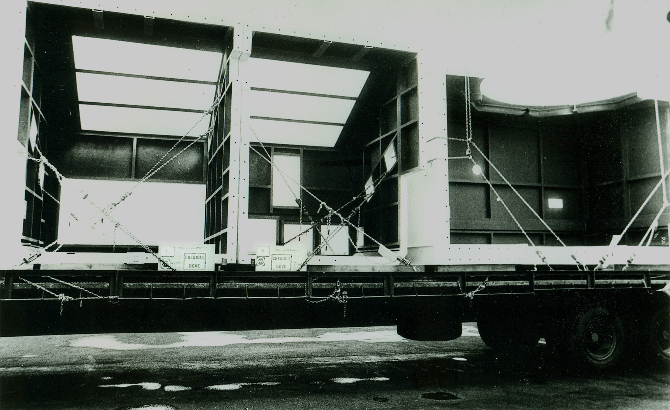 Figure 17. Credible Dove, early 1985 |
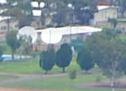 Figure 18. Antennas 87-A and 88-A, 23 January 2016. |
 Figure 19. Foundation for new radome (85-A) constructed in late 1984. |
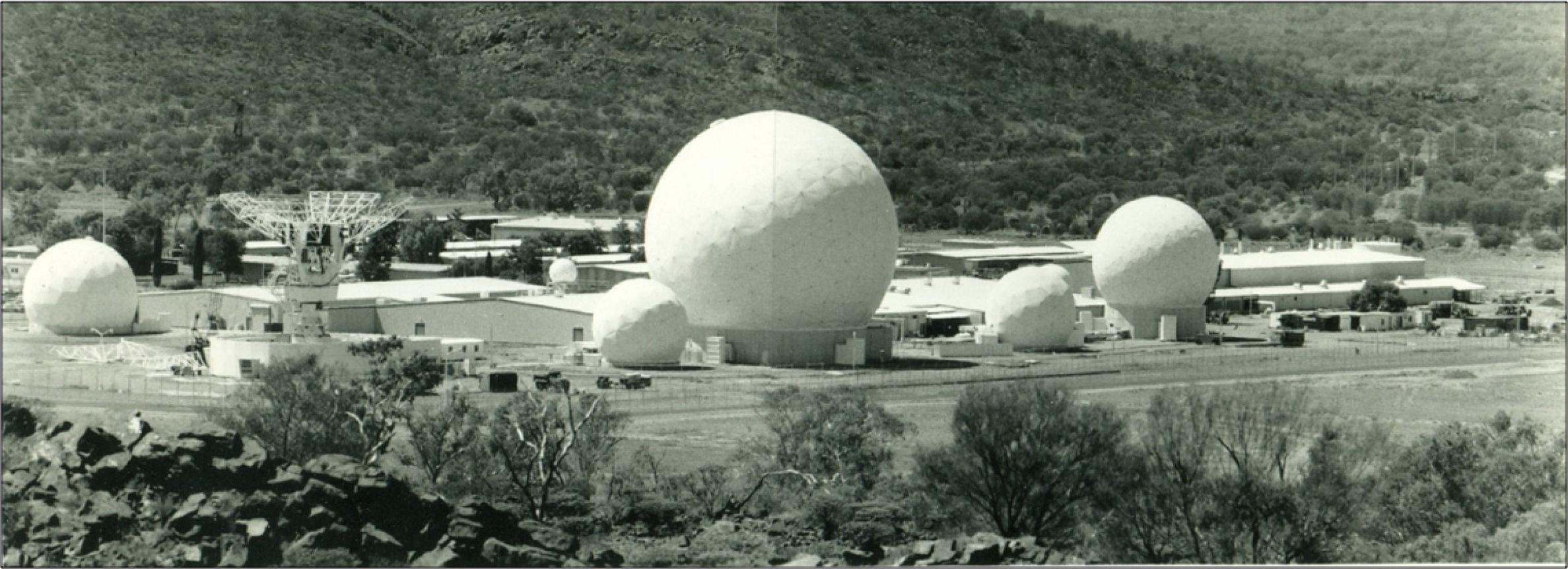 Figure 20. Pine Gap, mid-1985, with seven radomes and new large dish under construction (Antennas 73-A, 85-A under construction, 80-A, 77-A, 68-A, 71-A, 80-B and 68-B) |
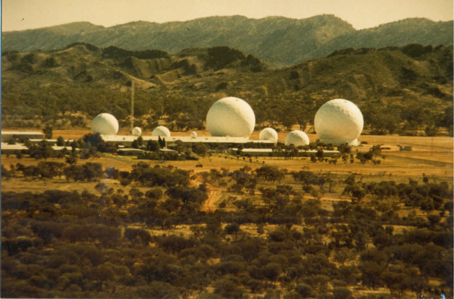 Figure 21. Eight radomes at Pine Gap, 1986 (Antennas 68-B, 80-B, 71-A, 80-A, 68-A, 77-A, 73-A and 85-A). |
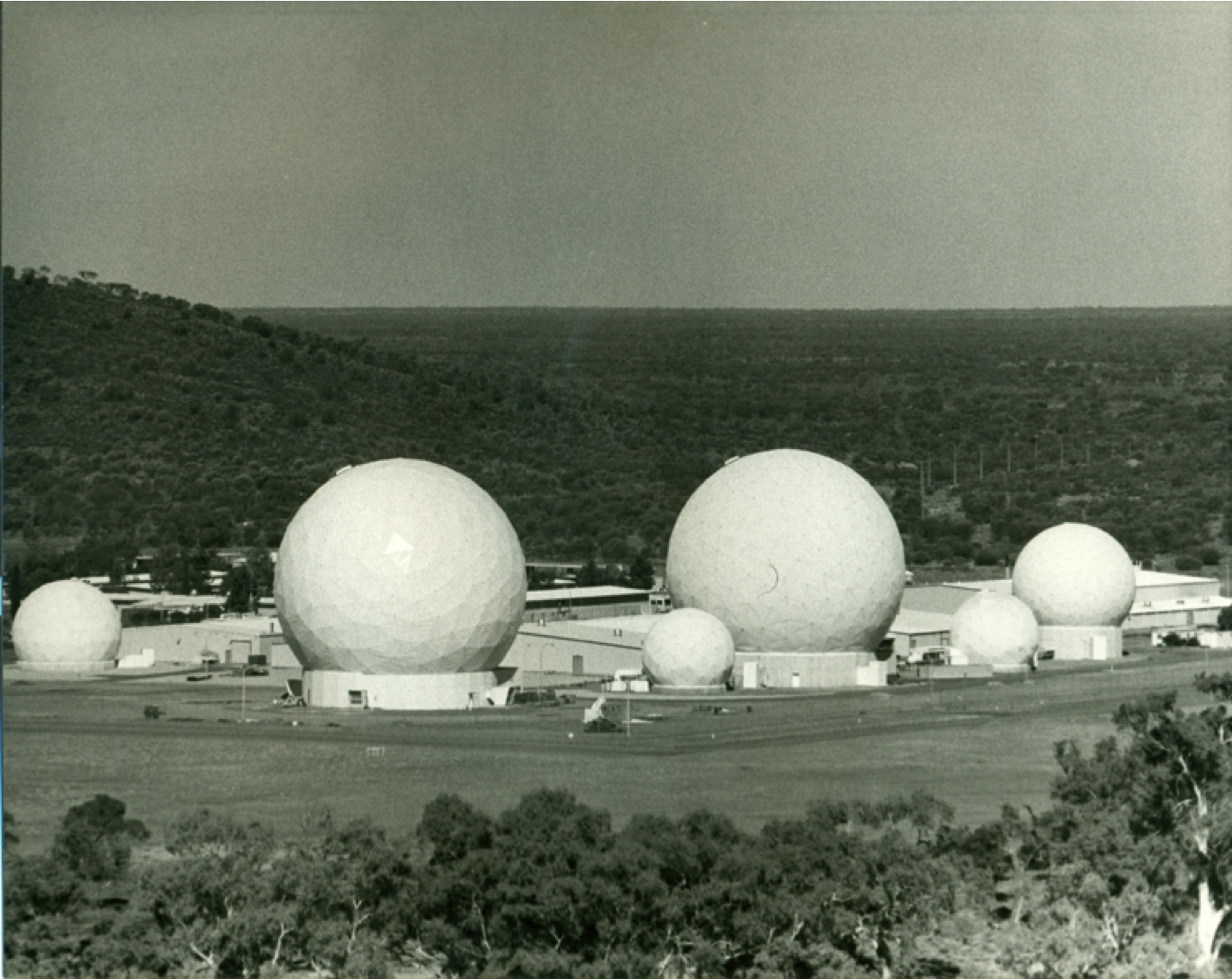 Figure 22. Radomes at Pine Gap, c 1986 (Antennas 73-A, 85-A, 77-A, 68-A, 71-A and 68-B). |
![Figure 23. Radomes at Pine Gap, c 1986 (Antennas 85-A, 80-A [half hidden on roof of the Operations Building], 77-A, 68-A, 71-A and 68-B).](https://nautilus.org/wp-content/uploads/2016/02/Figure-23.-Radomes-at-Pine-Gap-c-1986-Antennas-85-A-80-A-half-hidden-on-roof-of-the-Operations-Building-77-A-68-A-71-A-and-68-B.jpg) Figure 23. Radomes at Pine Gap, c 1986 (Antennas 85-A, 80-A [half hidden on roof of the Operations Building], 77-A, 68-A, 71-A and 68-B). |
 Figure 24. Radomes at Pine Gap in 1986 (Antennas 68-A, 71-A, 80-B, top of 73-A and 68-B). |
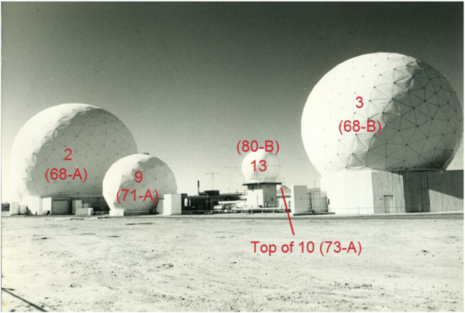 |
 Figure 25. Radomes at Pine Gap in 1986 (Antennas 68-B, 80-B, 71-A, 68-A 77-A and 85-A). |
 Figure 25. Radomes at Pine Gap in 1986 (Antennas 68-B, 80-B, 71-A, 68-A 77-A and 85-A) |
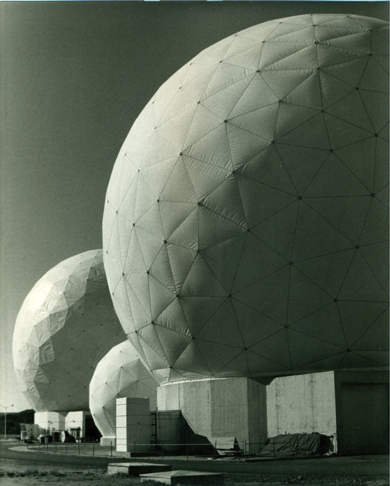 Figure 26. Radomes at Pine Gap in 1986 (Antennas 85-A, 77-A and 68-A). |
 Figure 26. Radomes at Pine Gap in 1986 (Antennas 85-A, 77-A and 68-A) – annotated |
 Figure 27. Radomes at Pine Gap, c 1991. |
 Figure 27. Radomes at Pine Gap, c 1991 – annotated. |
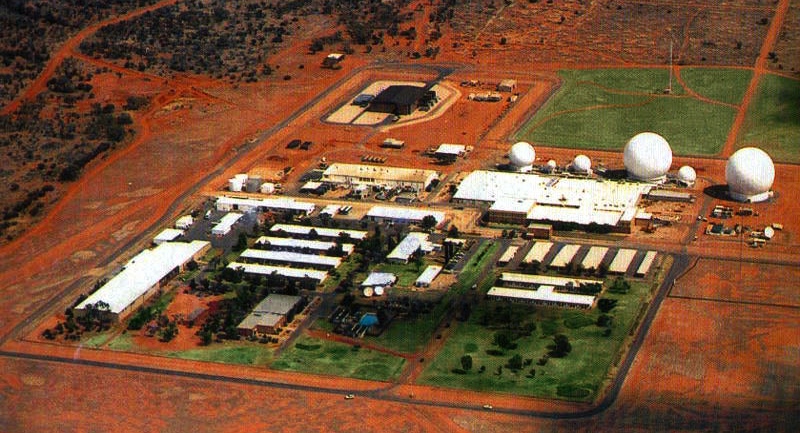 Figure 28. Pine Gap, c 1997 (Antennas 68-B, 80-B, 80-A on the roof of the Operations Building, 71-A, 68-A, 77-A, 85-A and 86-A, with 87-A and 88-A in Administration/Recreation area). |
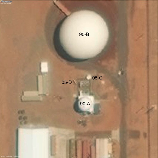 Figure 29. Antennas 90-A and 90-B, TerraServer imagery, 7 October 2014 |
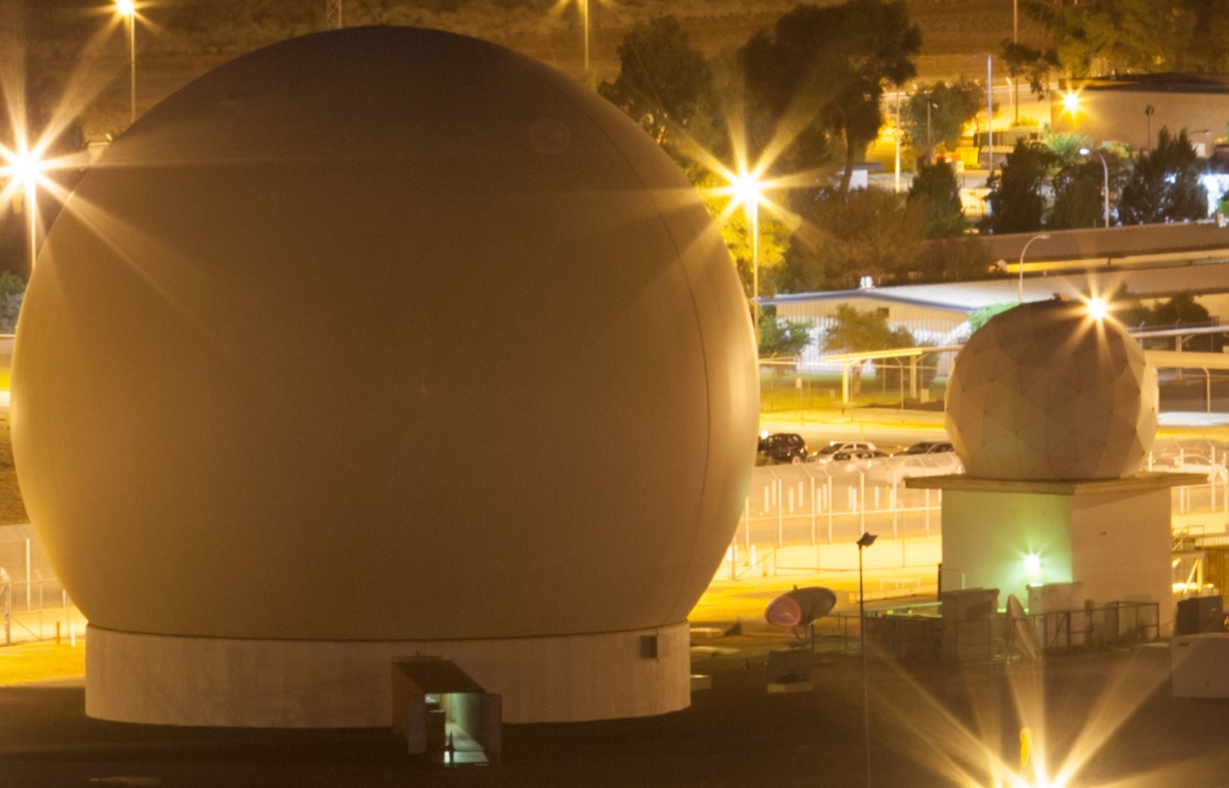 Figure 30. |
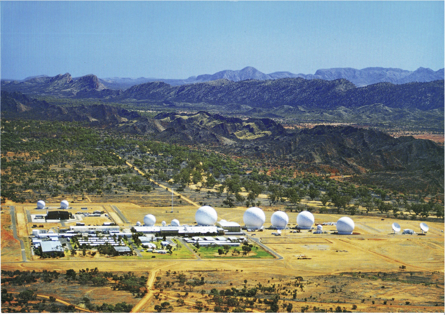 Figure 31. Pine Gap, 1999 |
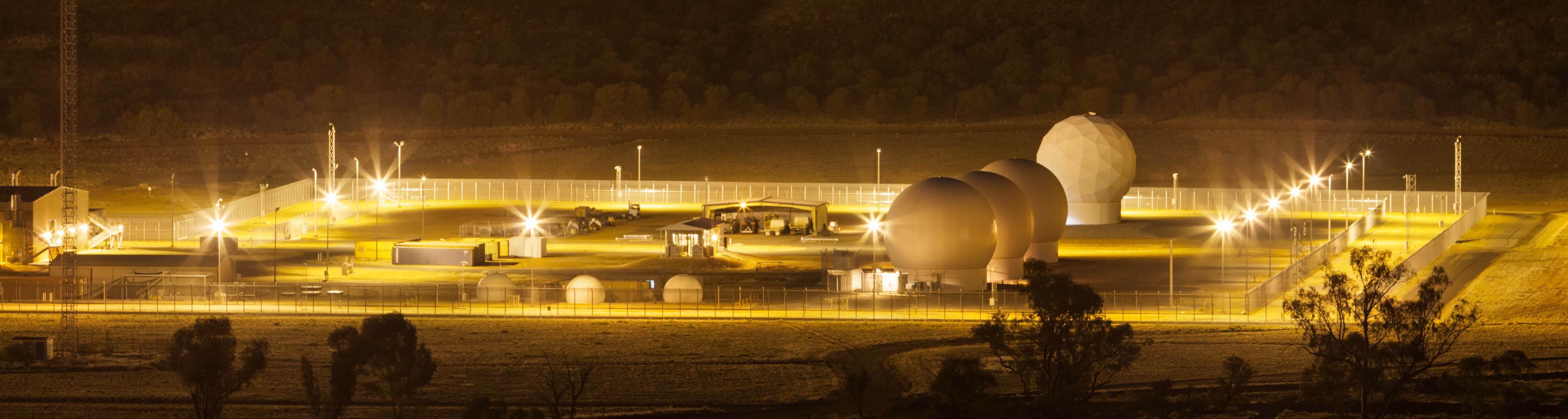 Figure 32. |
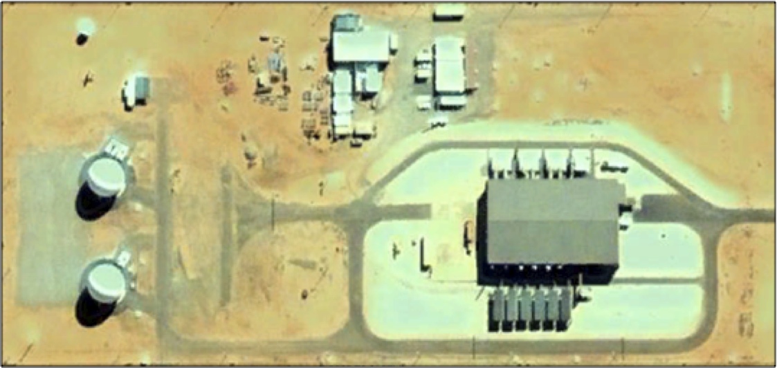 Figure 33. DSP/SBIRS RGS compoundGoogle Earth imagery, 11 August 2005 |
 Figure 34. DSP/SBIRS RGS compound, 2012 Here.com imagery |
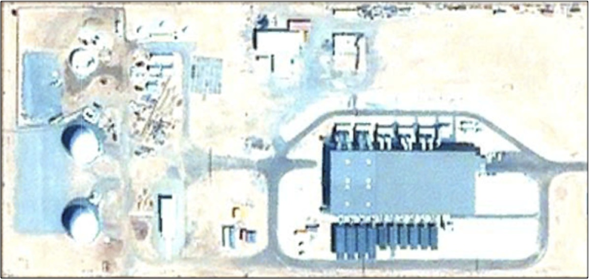 Figure 35. |
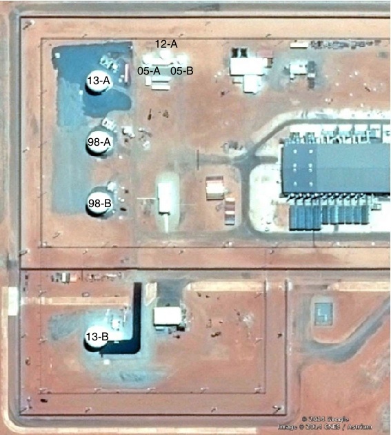 Figure 36. |
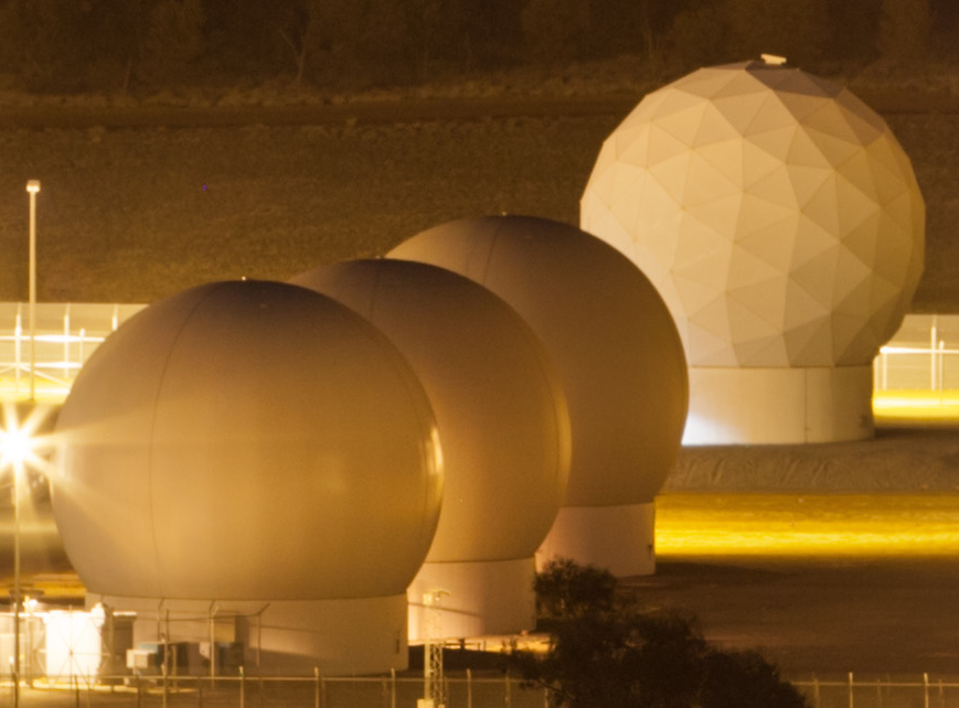 Figure 37. DSP/SBIRS |
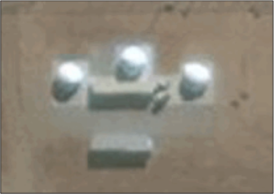 Figure 38. |
 Figure 39. |
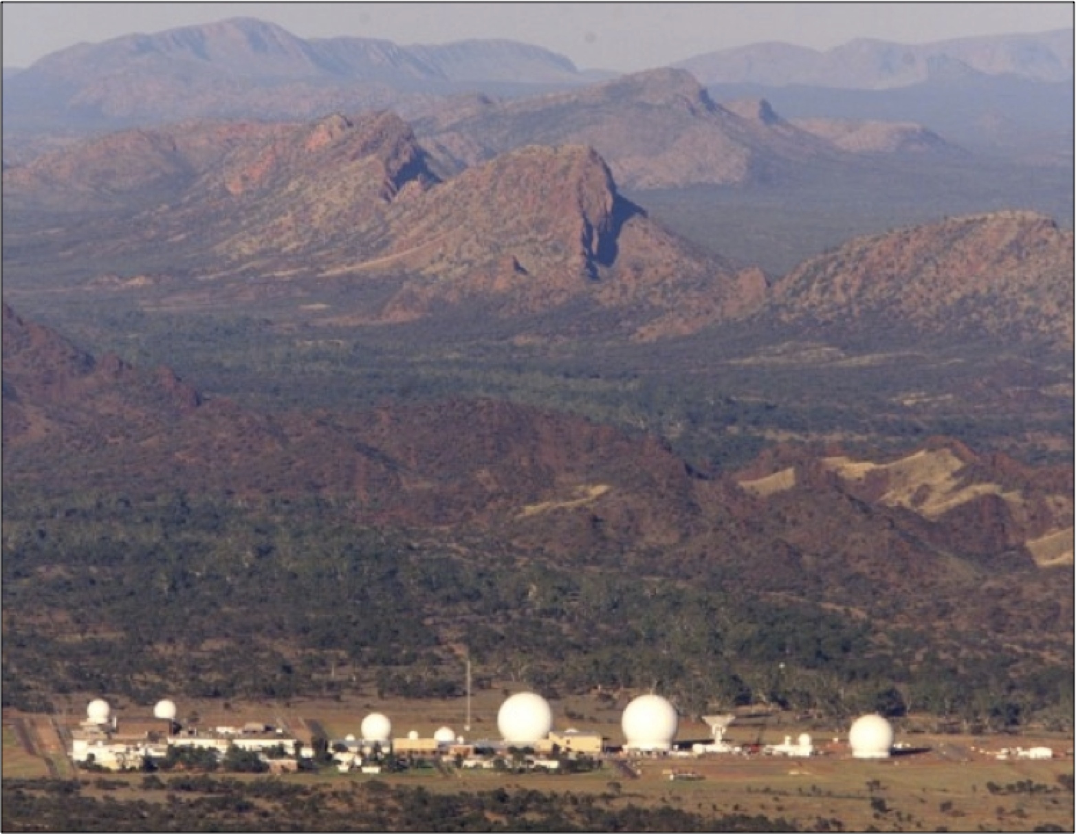 Figure 40. |
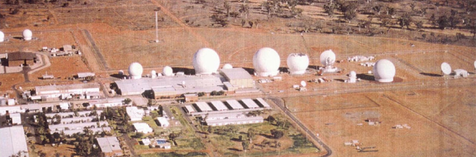 Figure 41. |
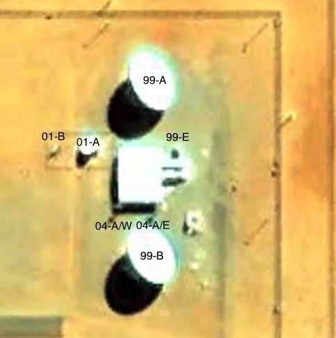 Figure 42. |
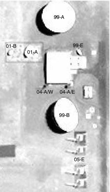 Figure 43. Antennas 99-A, 01-B, 01-A, 99-E, 04-A, 99-B and 05-E, |
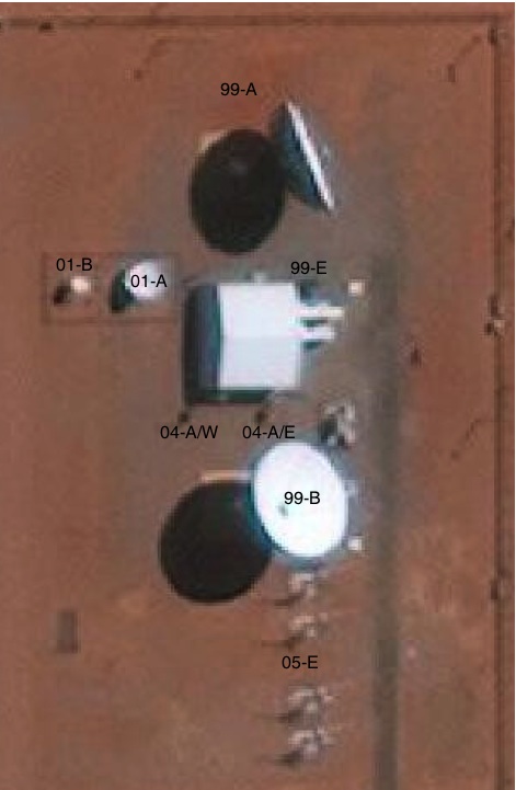 Figure 44. |
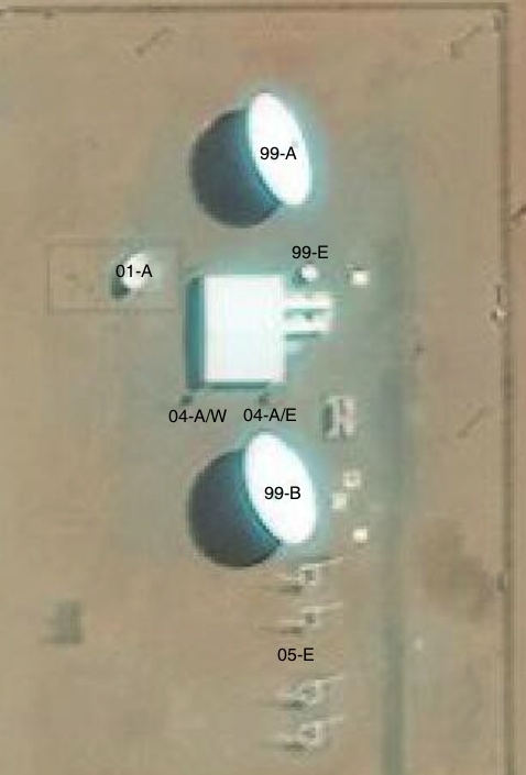 Figure 45. |
 Figure 46. |
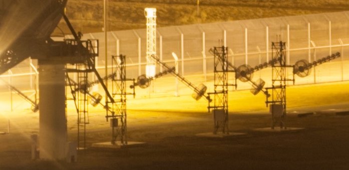 Figure 47. Helical array |
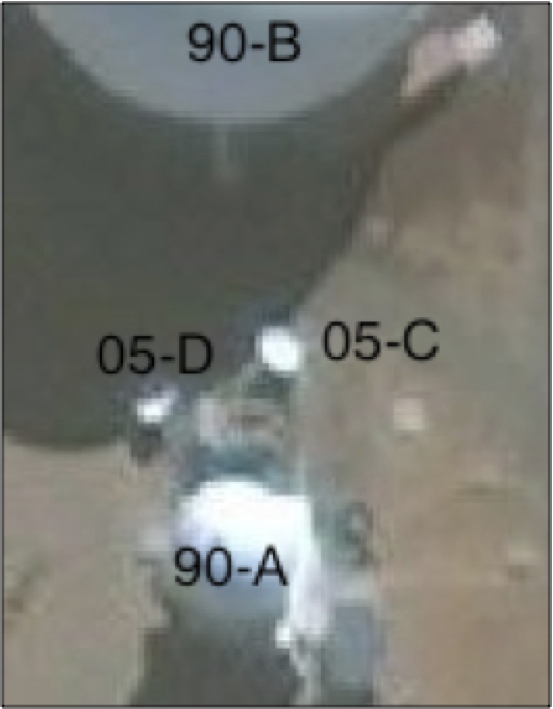 Figure 48. Two 4-metre dishes, Antennas 05-C and 05-D, TerraServer imagery, 10 September 2010 |
 Figure 48b. Antennas 05-C and 05-D, Terraserver imagery, 20 September 2012 |
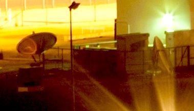 Figure 49. Two 4-metre dishes, Antennas 05-C and 05-D |
 Figure 50. |
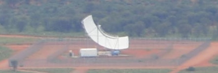 Figure 51. |
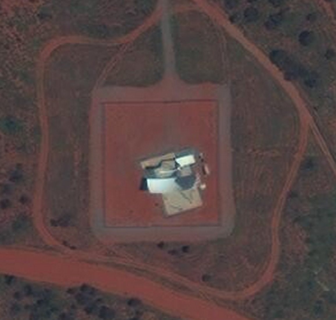 Figure 52. |
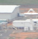 Figure 53a. Antenna 11-A |
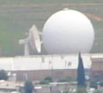 Figure 53b. Antenna 11-A, 23 January 2016. |
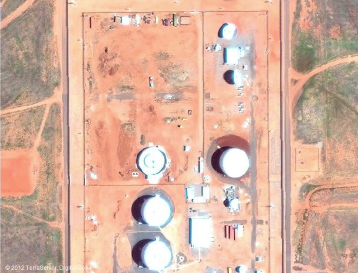 Figure 54. |
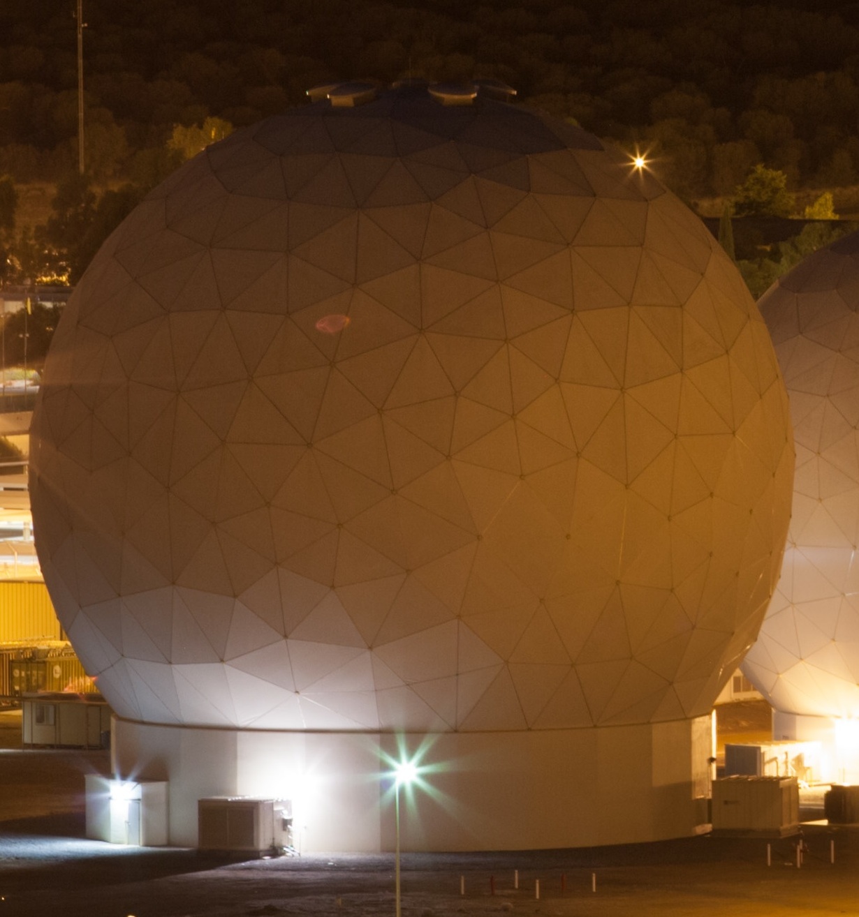 Figure 55. Antenna 10-A |
 Figure 56. |
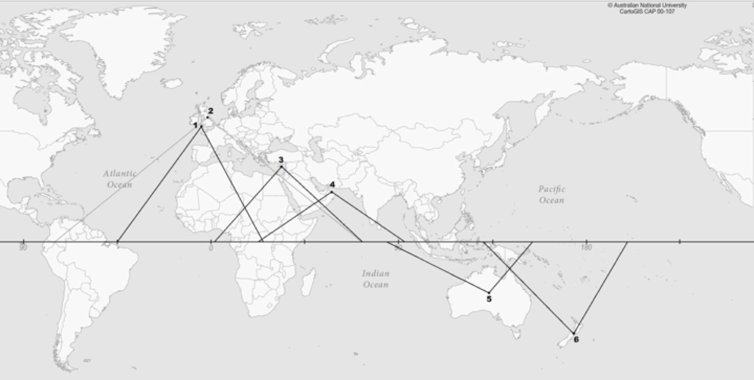 Map 1. |
|||