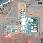
 Figure 1. Antenna systems at Pine Gap, Google Earth imagery, 6 November 2015.
Note: for antenna identification system see Desmond Ball, Bill Robinson and Richard Tanter, The Antennas of Pine Gap, Nautilus Institute, Special Reports, February 2016. |
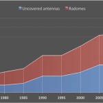 Figure 2.
Number of antenna systems at Pine Gap,
1970-2015 |
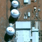 Figure 3. Pine Gap signals intelligence compound, 2012 – annotated |
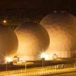 Figure 4.
Principal SIGINT and FORNSAT/COMSAT parabolic antennas in radomes
(Antennas 90-A, 10-A, 99-D, 99-C, 85-A, 77-A, 68-A, 71-A, 68-B)
Source: Kristian Laemmle-Ruff, (Attribution – NonCommercial CC BY-NC). |
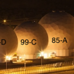 Figure 4. Principal SIGINT and FORNSAT/COMSAT parabolic antennas in radomes
(annotated)
Source: Kristian Laemmle-Ruff, (Attribution – NonCommercial CC BY-NC). |
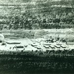 Figure 5. Two radomes at Pine Gap, 1968-69 (Antennas 68-A and 68-B) |
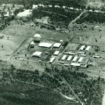 Figure 6. Five radomes at Pine Gap, 1973-77 (Antennas 68-B, 71-A, 68-A and 73-A; 69-B not visible – collimation tower to left of 68-A) |
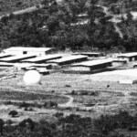 Figure 7. Four radomes at Pine Gap, 1969-71 (Antennas 69-A, 68-A, 69-B and 68-B) |
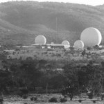 Figure 8. Five radomes at Pine Gap, 1971-77 (68-A, 73-A, 71-A, 69-B and 68-B) |
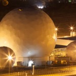 Figure 9. Antennas 77-A, 68-A, 71-A, 68-B
Source: Kristian Laemmle-Ruff, (Attribution – NonCommercial CC BY-NC). |
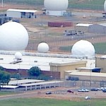 Figure 10. Antennas 68-B, 80-A (on Operations Building roof), 80-B, 71-A, 68-C (HF transmitter), 68-B, 77-A and 86-A, 23 January 2016 |
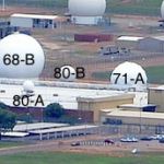 Figure 10. (annotated) Antennas 68-B, 80-A (on Operations Building roof), 80-B, 71-A, 68-C (HF transmitter), 68-B, 77-A and 86-A, 23 January 2016 |
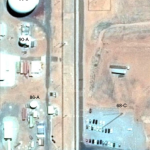 Figure 11. HF transmitter (68-C) and receiver (68-D) antennas at Pine Gap,
Google Earth imagery, 6 November 2015 |
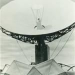 Figure 12. Ford Aerospace SCT-35 DSCS antenna system.
Source: Ford Aerospace |
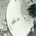 Figure 13. Ford Aerospace SCT-8 DSCS antenna system.
Source: Ford Aerospace |
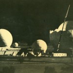 Figure 14. Six radomes, 1977 (Antennas 73-A, 68-B, 69-B, 71-A, 68-A and 77-A) |
![Figure 15. Six radomes, 1977 (Antennas 68-C [HF], 73-A, 68-B, 69-B, 71-A, 68-A and 77-A)](https://nautilus.org/wp-content/uploads/2016/02/Figure-15.-Six-radomes-1977-Antennas-68-C-HF-73-A-68-B-69-B-71-A-68-A-and-77-A-150x150.jpg) Figure 15. Six radomes, 1977 (Antennas 68-C [HF], 73-A, 68-B, 69-B, 71-A, 68-A and 77-A) |
![Figure 16. Seven radomes at Pine Gap, 1983 (Antennas 73-A, 77-A, 80-A [on the roof of the Operations Building], 68-A, 71-A, 80-B and 68-B). Source: ‘Concern Rises Over “Spy Role”’, Centralian Advocate, 18 January 1985, (photograph taken January-July 1983).](https://nautilus.org/wp-content/uploads/2016/02/Figure-16.-Seven-radomes-at-Pine-Gap-1983-Antennas-73-A-77-A-80-A-on-the-roof-of-the-Operations-Building-68-A-71-A-80-B-and-68-B-150x150.jpg) Figure 16. Seven radomes at Pine Gap, 1983 (Antennas 73-A, 77-A, 80-A [on the roof of the Operations Building], 68-A, 71-A, 80-B and 68-B).
Source: ‘Concern Rises Over “Spy Role”’, Centralian Advocate, 18 January 1985,
(photograph taken January-July 1983). |
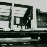 Figure 17. Credible Dove, early 1985 |
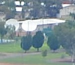 Figure 18. Antennas 87-A and 88-A, 23 January 2016.
Source: Felicity Ruby, (Attribution – NonCommercial CC BY-NC). |
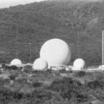 Figure 19. Foundation for new radome (85-A) constructed in late 1984.
Source: Source: ‘Concern Rises Over “Spy Role”’, Centralian Advocate, 18 January 1985. |
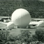 Figure 20. Pine Gap, mid-1985, with seven radomes and new large dish under construction (Antennas 73-A, 85-A under construction, 80-A, 77-A, 68-A, 71-A, 80-B and 68-B) |
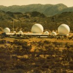 Figure 21. Eight radomes at Pine Gap, 1986 (Antennas 68-B, 80-B, 71-A, 80-A, 68-A, 77-A, 73-A and 85-A). |
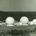 Figure 22. Radomes at Pine Gap, c 1986 (Antennas 73-A, 85-A, 77-A, 68-A, 71-A and 68-B).
Source: Department of Defence Public Relations, Canberra, Ref. No. CANA/85 / 315/17. |
![Figure 23. Radomes at Pine Gap, c 1986 (Antennas 85-A, 80-A [half hidden on roof of the Operations Building], 77-A, 68-A, 71-A and 68-B).](https://nautilus.org/wp-content/uploads/2016/02/Figure-23.-Radomes-at-Pine-Gap-c-1986-Antennas-85-A-80-A-half-hidden-on-roof-of-the-Operations-Building-77-A-68-A-71-A-and-68-B-150x150.jpg) Figure 23. Radomes at Pine Gap, c 1986 (Antennas 85-A, 80-A [half hidden on roof of the Operations Building], 77-A, 68-A, 71-A and 68-B). |
 Figure 24. Radomes at Pine Gap in 1986 (Antennas 68-A, 71-A, 80-B, top of 73-A and 68-B).
Source: Department of Defence Public Relations, Canberra, Ref. No. CANA/85 / 315/24. |
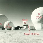 |
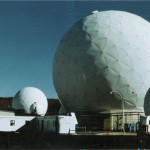 Figure 25. Radomes at Pine Gap in 1986 (Antennas 68-B, 80-B, 71-A, 68-A 77-A and 85-A).
Source: Department of Defence. |
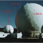 Figure 25. Radomes at Pine Gap in 1986 (Antennas 68-B, 80-B, 71-A, 68-A 77-A and 85-A) |
 Figure 26. Radomes at Pine Gap in 1986 (Antennas 85-A, 77-A and 68-A).
Source: Department of Defence Public Relations, Canberra,
Ref. No. CANA/85 / 315/21. |
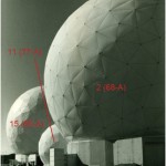 Figure 26. Radomes at Pine Gap in 1986 (Antennas 85-A, 77-A and 68-A) – annotated
Source: Department of Defence Public Relations, Canberra,
Ref. No. CANA/85 / 315/21. |
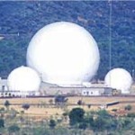 Figure 27. Radomes at Pine Gap, c 1991.
(Antennas 68-B, 80-B, 71-A, 84-A HF LPA, 73-A, 68-A, 77-A, collimation tower behind 85-A, 85-A, 86-A without radome in front of 85-A, and 90-A).
Source: Erwin Chlanda, ‘Spy base and Kindergarten: Are they above the law?’ Alice Springs News Online, 12 December 2012,
at http://www.alicespringsnews.com.au/2012/12/12/spy-base-and-kindergarten-are-they-above-the-law/. |
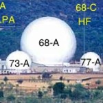 Figure 27. Radomes at Pine Gap, c 1991 – annotated.
Source: Erwin Chlanda, ‘Spy base and Kindergarten: Are they above the law?’ Alice Springs News Online, 12 December 2012,
at http://www.alicespringsnews.com.au/2012/12/12/spy-base-and-kindergarten-are-they-above-the-law/. |
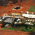 Figure 28. Pine Gap, c 1997 (Antennas 68-B, 80-B, 80-A on the roof of the Operations Building, 71-A, 68-A, 77-A, 85-A and 86-A, with 87-A and 88-A in Administration/Recreation area).
Source: Stan and Holly Deyo, ‘Pine Gap: America’s Tribute to Nikola Tesla’,
at http://millennium-ark.net/News_Files/Newsletters/News000722/News000722.html. |
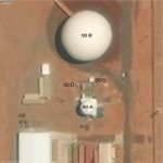 Figure 29. Antennas 90-A and 90-B, TerraServer imagery, 7 October 2014 |
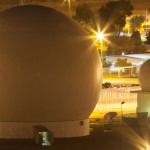 Figure 30.
Antennas 90-B, 05-C, 05-D and 90-B.
Source: Kristian Laemmle-Ruff, (Attribution – NonCommercial CC BY-NC). |
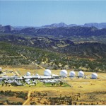 Figure 31. Pine Gap, 1999
Source: Department of Defence, supplied to Ms Tanya Plibersek, MHR, accompanying ‘Defence: Pine Gap’, Hansard (House of Representatives), 28 May 2002, p. 2555. |
 Figure 32.
The Relay Ground Station compound,
(Antennas 05-B, 12-A, 05-A, 13-A, 98-A, 98-B and 13-B)
Source: Kristian Laemmle-Ruff, (Attribution – NonCommercial CC BY-NC). |
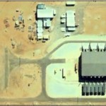 Figure 33. DSP/SBIRS RGS compoundGoogle Earth imagery, 11 August 2005 |
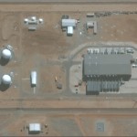 Figure 34. DSP/SBIRS RGS compound, 2012 Here.com imagery |
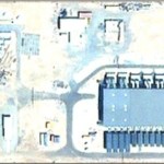 Figure 35.
DSP/SBIRS RGS compound Google Earth imagery, 9 January 2013 |
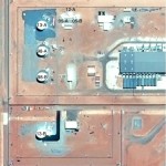 Figure 36.
DSP/SBIRS RGS compound Google Earth imagery, 2 October 2014 |
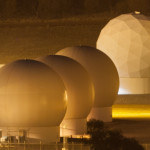 Figure 37. DSP/SBIRS
overhead persistent infrared antennas,
(Antennas 13-A, 98-A, 98-B and 13-B)
Source: Kristian Laemmle-Ruff, (Attribution – NonCommercial CC BY-NC). |
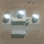 Figure 38.
Three 5.5-metre STSS radomes, 2012
(Antennas 05-A, 12-A and 05-B |
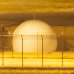 Figure 39.
Antennas 05-B, 12-A and 05-A
Source: Kristian Laemmle-Ruff, (Attribution – NonCommercial CC BY-NC). |
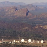 Figure 40.
FORNSAT radomes under construction, early 1999
Source: Philip Dorling, ‘Pine Gap drives US drone kills’, Sydney Morning Herald, 21 July 2013 (photograph supplied), at
http://www.smh.com.au/national/pine-gap-drives-us-drone-kills-20130720-2qbsa.html. |
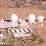 Figure 41.
FORNSAT radomes (99-C and 99-D) under construction, early 1999
Source: ‘“Pine Gap”, Australian Map – Military Communications, Spy Bases and Nuclear Ship Ports’, at
http://australianmap.net/pine-gap/. |
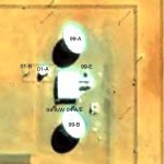 Figure 42.
Antennas 99-A, 01-B, 01-A, 99-E, 04-A and 99-B Google Earth imagery, 8 September 2004 |
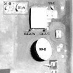 Figure 43. Antennas 99-A, 01-B, 01-A, 99-E, 04-A, 99-B and 05-E,
TerraServer imagery,
17 October 2009 |
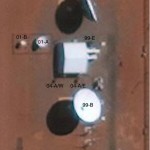 Figure 44.
Antennas 99-A, 01-B, 01-A, 99-E, 99-B, 04-A and 05-E
TerraServer imagery, 20 September 2012 |
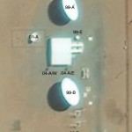 Figure 45.
Antennas 99-A, 01-A, 99-E and 99-B TerraServer imagery, 8 October 2013 |
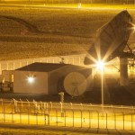 Figure 46.
DSP/SBIRS communications antennas
Antennas 99-A, 99-E, 01-A, 99-B, 04-A (helical array), 99-B and 05-E (helical array)
Source: Kristian Laemmle-Ruff, (Attribution – NonCommercial CC BY-NC). |
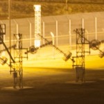 Figure 47. Helical array
(Antenna 05-E in two sets of two to right of 99-B)
Source: Kristian Laemmle-Ruff, (Attribution – NonCommercial CC BY-NC). |
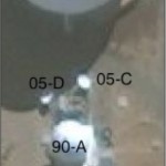 Figure 48. Two 4-metre dishes, Antennas 05-C and 05-D, TerraServer imagery, 10 September 2010 |
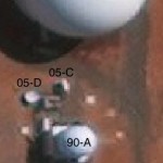 Figure 48b. Antennas 05-C and 05-D, Terraserver imagery, 20 September 2012 |
 Figure 49. Two 4-metre dishes, Antennas 05-C and 05-D
Source: Kristian Laemmle-Ruff, (Attribution – NonCommercial CC BY-NC). |
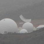 Figure 50.
Antenna 08-A, Torus multi-beam antenna
12 October 2013
(Antennas 68-A, 71-A, 68-B, 11-A, and 08-A at rear)
Source: Richard Tanter, (Attribution – NonCommercial CC BY-NC). |
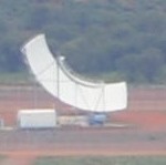 Figure 51.
Antenna 08-A, Torus multi-beam antenna,
23 January 2016
Source: Felicity Ruby, (Attribution – NonCommercial CC BY-NC). |
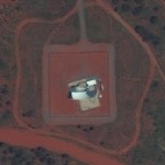 Figure 52.
Torus multi-beam antenna compound, TerraServer imagery,
January 2010 |
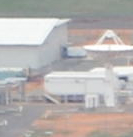 Figure 53a. Antenna 11-A
Source: Felicity Ruby, (Attribution – NonCommercial CC BY-NC). |
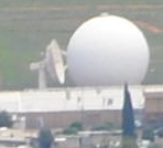 Figure 53b. Antenna 11-A, 23 January 2016.
Source: Felicity Ruby, (Attribution – NonCommercial CC BY-NC). |
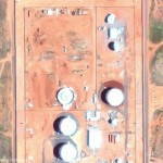 Figure 54.
Antenna 10-A commencing construction, TerraServer imagery,
22 January 2011 |
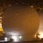 Figure 55. Antenna 10-A
Source: Kristian Laemmle-Ruff, (Attribution – NonCommercial CC BY-NC). |
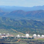 Figure 56.
Pine Gap from the southeast,
23 January 2016
Source: Felicity Ruby
(Attribution – NonCommercial CC BY-NC). |
 Map 1.
Torus sites and coverage of the geostationary satellite belt |
|
|
|
|
|
|
|
|
|
|
|
|
|
|
|
|
|
|
|
|
|
|
|


![Figure 15. Six radomes, 1977 (Antennas 68-C [HF], 73-A, 68-B, 69-B, 71-A, 68-A and 77-A)](https://nautilus.org/wp-content/uploads/2016/02/Figure-15.-Six-radomes-1977-Antennas-68-C-HF-73-A-68-B-69-B-71-A-68-A-and-77-A-150x150.jpg)
![Figure 16. Seven radomes at Pine Gap, 1983 (Antennas 73-A, 77-A, 80-A [on the roof of the Operations Building], 68-A, 71-A, 80-B and 68-B). Source: ‘Concern Rises Over “Spy Role”’, Centralian Advocate, 18 January 1985, (photograph taken January-July 1983).](https://nautilus.org/wp-content/uploads/2016/02/Figure-16.-Seven-radomes-at-Pine-Gap-1983-Antennas-73-A-77-A-80-A-on-the-roof-of-the-Operations-Building-68-A-71-A-80-B-and-68-B-150x150.jpg)


![Figure 23. Radomes at Pine Gap, c 1986 (Antennas 85-A, 80-A [half hidden on roof of the Operations Building], 77-A, 68-A, 71-A and 68-B).](https://nautilus.org/wp-content/uploads/2016/02/Figure-23.-Radomes-at-Pine-Gap-c-1986-Antennas-85-A-80-A-half-hidden-on-roof-of-the-Operations-Building-77-A-68-A-71-A-and-68-B-150x150.jpg)


