
Toshiari Saegusa
July 7, 2017
I. INTRODUCTION
In this essay, Toshiari Saegusa reviews the evolution of nuclear spent fuel (SF) storage technology and in particular, the safety, economic, and security issues associated with use of dry cask storage for nuclear spent fuel. He concludes: “From technical and economic points of view, SF needs to be cooled efficiently in the reactor pool during the first decade following discharge from nuclear reactors, and thereafter it may be stored in dry casks. Both the metal cask and pool storage methods have been implemented conforming to the regulatory requirements for nuclear safety and security in Japan. CRIEPI’s study of SF storage costs showed that the cask storage method is more economical than the pool storage method. The cost of required additional countermeasures for security will emphasize the economic advantage of the cask storage method.”
Toshiari Saegusa is Research Advisor Emeritus, Central Research Institute of Electric Power Industry, Tokyo
This Special Report was prepared for the Project on Reducing Risk of Nuclear Terrorism and Spent Fuel Vulnerability In East Asia. It was presented at a Nautilus Institute Workshop at International House, Tokyo, September 14-15, 2015, funded by The Macarthur Foundation.
The views expressed in this report do not necessarily reflect the official policy or position of the Nautilus Institute. Readers should note that Nautilus seeks a diversity of views and opinions on significant topics in order to identify common ground.
Banner Image Credit:: Traditional oak barrels made by Chilean cooperage Tonelería Nacional, by Gerard Prins under Creative Commons BY-SA 3.0, from https://commons.wikimedia.org/w/index.php?curid=14955249
II. NAPSNET SPECIAL REPORT BY TOSHIARI SAEGUSA
METAL CASK STORAGE AS COMPARED WITH POOL STORAGE OF SPENT NUCLEAR FUEL IN JAPAN
July 7, 2017
1. Outline of metal cask storage
Table 1 shows the history of technological development of nuclear spent fuel (SF) storage globally[1]). The first applications of SF storage began with storage of fuels discharged from reactors in pools located at (AR) and away from reactor (AFR) sites, and other current major dry storage methods, including placing SF assemblies in metal and concrete casks, were subsequently developed.
The dual-purpose metal cask storage has potential issues of compliance with future SFs transport regulations after SF has been stored in the casks for several decades. If transport regulations do not change significantly, this issue will be negligible. Depending on the extent of regulation changes, the dual-purpose cask may not be permissible for use for transportation with its original design. The SF may have to be unloaded from the dual-purpose cask and placed in separate casks approved for transport before it can be moved. As a result, a merit of the dual-purpose cask may be lost. On the other hand, concrete cask storage methods would likely not pose issues of compliance with future transport regulations because SF after storage would likely be transported by separate transport casks to their destination.
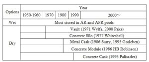
Table 1: History of technological development of SF storage method
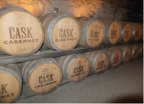
Figure 1: Casks storing wine
2. Background and needs
The metal cask was originally developed as a transport cask for radioactive material, and was (and is) designed to withstand test conditions related to potential transport accidents, including mechanical impact and fire accidents, while maintaining safety functions of sub-criticality, confinement, heat removal, and shielding. When the metal cask is used for storage, it is normally filled with helium gas for heat removal and to prevent oxidation of the fuel elements. The metal cask also has a double lid structure employing metal gaskets to give durability and a monitoring function to the confinement performance. Traditionally, the word “cask” was used to denote a small wooden barrel used for storing wine and other goods (as shown in Figure 1). Metal cask storage has merits of modularity, in that allows expansion of storage capacity as needed, and of low investment risk in that it requires relatively modest initial investment and relatively low ongoing investment for operations and maintenance.
3. Design concept with safety functions
A metal cask is a container used for the transport and storage of nuclear reactor SF. It consists of a main body, lids, a basket to hold the SF, and other components, and is tied down to the floor of the storage facility as needed. Figure 2 shows an example of the design concept. The metal cask has four safety functions, namely 1) confinement function, 2) shielding function, 3) criticality preventing function, 4) heat removal function.
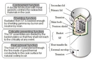
Figure 2: Example of metal cask and lid structure for confinement (Cask diameter: 2.5 m, Height: 5 m, Total weight with fuel: 120 t) (Accommodates 26 PWR or 69 BWR assemblies)
In Japan, by the year 2013, two metal cask storage facilities had been installed within the premises of nuclear power plants. One is at the Fukushima Daiichi Nuclear Power Plant of Tokyo Electric Power Company, which has been operated since 1995 using nine storage-only metal casks. This facility was originally used for storing transport casks in a horizontal attitude prior to sea transportation. These casks were inundated by the Tsunami at resulting from the Great East Japan Earthquake on March 11, 2011. The casks at Fukushima Daiichi maintained their integrity and fuel safety functions during and after the tsunami, and were subsequently moved to a temporary storage facility (see Figure 3) on the same premises after stringent inspections[2]). In the temporary storage facility, each cask is covered with a self-shielded concrete module. The modules were placed on an improved soil foundation. In the modules, the casks were tied down to the support frames with bolts. The casks are handled by a crane with a double lifting device. The current number of casks in the temporary storage facility at Fukushima Daiichi is 50, and will be increased by 15. Among those casks, 20 casks are for storage only and the rest are for transport and storage.
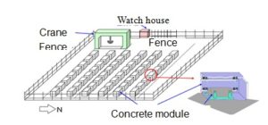
Figure 3: Outline of temporary dry cask storage facility
(Provided by Tokyo Electric Power Co, Inc.)
The other SF cask storage facility in Japan is on the premises of the Tokai Daini Nuclear Power Plant , operated by the Japan Atomic Power Company, and has been operated using storage-only casks since 2001 (see Figure 4). The casks at Tokai are set to stand upright and are tied down on the floor. The total capacity is 24 casks in the Tokai facility[3]). In the future, a new plan has been announced to store metal casks for transport and storage in the premises of the Hamaoka Nuclear Power Plant, operatied by Chubu Electric Power Company. Chubu Electric plans to store SF with a heavy metal content of 400 tU at the site[4]).
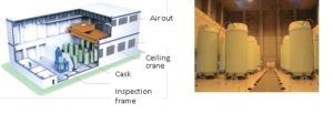
Figure 4: Design concept of cask storage facility to be installed by Japan Atomic Power Company, and the layout of the storage-only casks in the facility (Provided by Japan Atomic Power Company)
In addition, the Recyclable Fuel Storage Company (RFS), established jointly by the Tokyo Electric Power Company and the Japan Atomic Power Company, is constructing an interim storage facility outside the premises of the nuclear power plant at Mutsu city of Aomori prefecture[5]). The storage building is built on a foundation supported by piles, 130 m in length, 60 m in width, and 30 m in height, and stores 3,000 tU of SF using 288 metal casks designed for transport and storage. The Mutsu SF Storage Facility is planned for an ultimate capacity of are planning to store 5,000 tU in total, with SF remaining in storage finally for 50 years (see Figures 5 and 6).
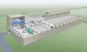
Figure 5: Image of interim storage facility (Provided by RFS)
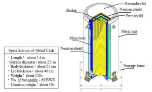
Figure 6: Example of concept of transport and storage cask to be stored in the interim storage facility (Copyright: RFS)
With regard to experience in countries outside Japan, cask storage has been implemented in the USA, Germany, Spain, and other places. In the USA, the Yucca Mountain project to dispose of SF in a long-term geological repository has been cancelled. Following a study by the Blue Ribbon Commission on America’s Nuclear Future, formed by the Secretary of Energy at the request of the President of the USA, the Department of Energy announced a plan to operate a pilot plant for an interim storage facility by 2021, a large scale interim storage facility by 2025, and a disposal facility by 2048[6]). Until that time, SF continues to be stored on the premises of US power plants. In the USA, the premises of nuclear power plant are typically large, and as a consequence storage buildings are note needed to reducing the radiation level at the site boundary. US at-reactor cask facilities store casks vertically on concrete pads outdoors (Figure 7).
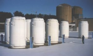
Figure 7: Metal cask storage in USA(Prairie Island NPP) (Copyright TN)
In Germany, interim storage facilities were built and commenced operation (Figure 8) in Gorleben and Ahaus, but after 2005 transportation of SF was prohibited by law and SF is now being stored on the premises of the nuclear power plants[7]). In addition, reprocessed high level wastes are being stored in Gorleben.
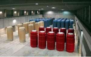
Figure 8: Interim storage facility at Gorleben (Copyright GNS)
4. Economic comparison with pool storage
Economic comparisons of metal cask storage and pool storage including sensitivity analyses with respect to storage duration, and other parameters were carried out. This SF storage economics study was carried out about 15 years ago as a reference for the selection of storage methods in advance of commercialization of away from reactor (AFR) storage of SF in Japan[8]).
(1) Index of economic performance
Unit storage cost was employed as an index of economic performance, which is defined at the cost required to store a unit of SF, $/kgU. The unit storage cost was defined further as a levelized cost based on the discounted cash flow for income and expenditures that has typically been used in CRIEPI’s economic studies of SF storage[9]). The levelized cost is calculated as follows.
The total expenditure [ΣCt/(1+i)t] for the expense (Ct) for the construction, operation, etc. is equal to the total income [ΣQt/(1+i)t] that was is a levelized value at a reference year t, (expressed as a constant storage unit cost (C) x amount of SF received by the storage facility (Qt)), as defined by the following equation.
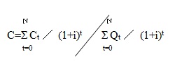
where,
C: Unit storage cost expressed in real (inflation-adjusted) monetary units [$/kgU]
Ct: Expenditure in the year t (expressed in by real prices) [$]
Qt: Amount of SF received by the storage facility in the year t [kgU]
i: Real discount rate [1/year]
t: Year of the expenditure in the assumed storage scenario
(2) Preconditions for evaluation
1) Storage facilities: Pool storage facility and metal cask storage facility (AFR) (Figures 9 and 10).
Fuel conditions: Burn-up of the SF was assumed to be 40 GWd/t. The ratio of storage of boiling water reactor and pressurized water reactor (BWR and PWR) fuel was equal to the ratio of the power generation by the two reactor types in Japan, 55:45.
2) Amount of storage and duration: 3000 tU/5000 tU/10000 tU, and 40 years.
3) Discount rate: 5%/year
The discount rate is defined as a rate to determine the required present value of a stream of costs or income, taking account of the performance of business, real increases in prices, the money rate, and other conditions. For instance, when a $ 10 K cost is expected to be incurred in 10 years, $ 6.1 K should be set aside today to pay that future cost, assuming the discount rate is 5 %/yr.
$10 K/(1+0.05)10 ≒ $6.1 K
4) Power generating efficiency: 0.33
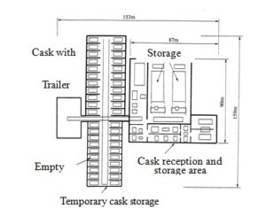
Figure 9: Design concept of pool storage facility (5,000 tU) (AFR)
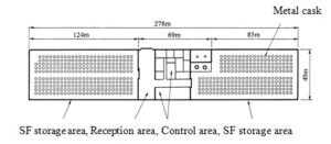
Figure 10: Design concept of cask storage facility (5,000 tU) (AFR)
(3) Results of evaluation
1) Influence of storage method and amount of storage on economics
It was found that when the storage capacity is small, the unit storage cost using the pool method is more expensive than using the metal cask storage method. As the storage amount is increased, the unit storage cost for the metal cask storage method approaches \ 3,000/kgU (Figure 11). This is because the change in storage expense due to the increase in the storage capacity is not linear for the case of the pool storage method. In the case of cask storage method, the increase of the storage amount does not contribute significantly to the unit cost of storage, that is, the storage unit cost is almost constant for cask storage because of the structure of the cask storage costs.
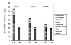
Figure 11: Example of comparison of unit storage
2) Influence of the metal cask cost on SF storage economics
Metal cask costs constitute about 80 % of the unit storage cost of dry cask storage. If metal cask costs decrease, the overall cost of dry cask storage decreases significantly (Figure 12).
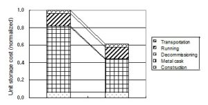
Reference case Metal cask cost 50% of Reference
Figure 12: Influence of metal cask cost on the unit storage cost (AFR)
3) Influence of storage costs on power generation costs
We performed a trial calculation of the implication of SF storage costs on total nuclear generation costs [\/kWh], that is the unit storage costs as calculated above divided by the amount of electricity generated by each unit of nuclear fuel. The per-kWh storage cost was \ 0.09/kWh using the metal cask storage method and \ 0.15/kWh using the pool storage method assuming application to 5-year cooled SF (Table 2). The difference between the two storage methods seems to be significant in absolute terms, but it is important to consider that the total power generation cost was \ 5.9/ kWh according to a report by the Nuclear Energy Subcommittee of the Advisory Committee for Natural Resources and Energy of the Japanese government as of December 1999, which means that of the total electricity costs at that time, about 1.5 % would be represented by storage costs using the metal cask and 2.5 % would be represented by storage cost using the pool storage method. The unit cost divided by the amount of power generation for SF with longer cooling time becomes smaller since the reference year from which the expense is levelized is set on the year of power generation and the year of storage becomes much later., reducing the levelized cost
4) Sensitivity analysis (Influence of the discount rate on the storage unit cost)
In the evaluation presented above, the discount rate was assumed to be 5 %/yr in the calculation. However, 5 % may be criticized to be high for use in evaluating SF storage options, since SF storage is carried out for the public benefit, and thus should be assigned a low discount rate. Accordingly, we studied cases in which the discount rate was set at 0 % and 2 % annually. In addition, making the assumption that the SF storage business may be similar to the general storage business by civilian industry, and thus discount rates used by typical private businesses may be appropriate, we studied cases of in which the discount rate was set at 8 % and 10 % per annum. The results of this sensitivity analysis indicated that the influence of the change of the discount rate on the storage unit cost was relatively small (Figure 13).
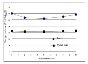
Figure 13: Influence of the discount rate on the unit storage cost
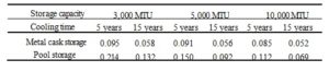
Table 2: Storage cost [\/kWh]
More detailed information on these results can be found in the literature[10]).
5. Japan’s Action plan for SF management [11])
On October 6, 2015, the Japanese government developed an action plan for SF management. Based on the plan, the government will promote to the expansion of SF storage capacity. Specifically, a council of government (represented by the Ministry of Economy, Trade, and Industry, or METI) and electric utilities will be established to promote expansion of SF storage. The government has requested that the utilities develop and publish “SF management programs”. The government will strengthen SF management by revising its subsidy program, in which dry cask storage facilities will be supported because of their easy maintenance, flexibility, transportability, and other benefits. The government will also promote completion of the reprocessing facility at Rokkasho and the interim storage facility at Mutsu city.
6. Discussion
6.1 Safety of cask storage and pool storage
Both metal cask storage and pool storage have been implemented in Japan, and conform to the current safety regulations. Figure 14 illustrates the safety functions and design concepts of each type of storage relative to existing safety requirements. It is noted that the pool storage method relies on active cooling systems for heat removal, whereas the cask storage method relies on passive cooling systems. After Japan’s nuclear safety review following the Fukushima accident, new safety regulations require multiple and diversified systems for power sources and cooling water sources. If the costs related to those additional safety regulations had been included in the economic comparison presented above, pool storage costs would have been shown to be even higher relative to costs for cask storage.
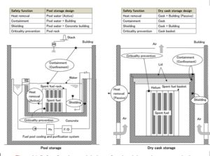
Figure 14: Safety functions and designs of pool and dry cask storage methods
From technical and economic points of view, SF needs to be cooled efficiently in reactor pools during the first decade after discharge from the reactor, and afterward it may be stored in dry casks, as implied by Figure 15.
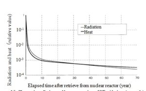
Figure 15: Change in radiation and heat generation of SF with time (example)
6.2 Security of cask storage and pool storage
(1) Energy Security
METI’s 2015 “Long-term Energy Supply and Demand Outlook”[12]) describes specific targets to improve energy security in Japan. After the East Japan Great Disaster of March 11, 2011, the energy self-sufficiency of Japan declined to about 6 % following the shutdown of the nation’s nuclear power plants. This is a quite low level as compared with the other OECD countries that lack abundant energy resources, including Spain (26.7 %), Italy (20. 1 %), and Korea (17.5 %), as shown in Figure 16. The Japanese government will aim to improve the nation’s energy self-sufficiency to exceed the level achieved before the disaster in 2011 (to about 25 %).
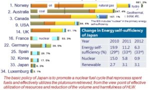
Figure 16: Energy Self-Sufficiency of OECD Countries (2012)[13]
The basic policy of Japan is to promote a nuclear fuel cycle that reprocesses SFs and effectively utilizes the plutonium recovered from the view point of both effective utilization of resources and reduction of the volume and harmfulness of High Level Wastes.
(2) Security in response to the threat of terrorist attacks using airplane impacts
Both cask storage and pool storage are designed and operated conforming to regulations for security that are based on IAEA INFCIRC/225/Rev 4 and 5[14]), which pertain to attacks on nuclear energy facilities using airplanes. Some of the relevant paragraphs in these regulations are as shown below.
Design Basis Threat (DBT) is defined as: The attributes and characteristics of potential insider and/or external adversaries, who might attempt unauthorized removal or sabotage, against which a physical protection system is designed and evaluated.
The appropriate State authorities should define the threat and associated capabilities in the form of a threat assessment and, if appropriate, a design basis threat. A design basis threat is developed from an evaluation by the State of the threat of unauthorized removal and of sabotage (para 3.34).
Requirements for the Process to Design a Physical Protection System against Sabotage
The operator should design a physical protection system that is effective against the defined sabotage scenarios and complies with the required level of protection for the nuclear facility and nuclear material (para 5.12).
In the case of sabotage or attempted sabotage which could affect a nuclear facility, two kinds of measures should be taken by the appropriate State response organizations and the operator (para 5.44).
As to the security of pool storage facilities currently SF pools are located at nuclear power plants and reprocessing plants in Japan. The new regulations put in place after the Fukushima accident requires that the physical protection for those plants includes countermeasures against terrorist airplane impact. With the application of countermeasures such as diversified and multiple electricity sources and water sources, pool storage facilities have conformed to the new security requirements related to the threat from a possible airplane impact used as a terrorist attack.. The cost for these types of countermeasures should be added to the storage unit costs estimated for pool storage in Figure 12.
As to the security of cask storage, regulations for spent nuclear fuel storage facilities using metal casks have not required countermeasures against terrorist airplane impacts. No countermeasures are required will be because metal casks have been shown to be robust and secure enough to withstand impacts consistent with airplane impacts.
The costs of the countermeasures for security required for SF pools will emphasize the economic advantages of cask storage.
7. Conclusion
From technical and economic points of view, SF needs to be cooled efficiently in the reactor pool during the first decade following discharge from nuclear reactors, and thereafter it may be stored in dry casks. Both the metal cask and pool storage methods have been implemented conforming to the regulatory requirements for nuclear safety and security in Japan. CRIEPI’s study of SF storage costs showed that the cask storage method is more economical than the pool storage method. The cost of required additional countermeasures for security will emphasize the economic advantage of the cask storage method.
III. ENDNOTES
[1] IAEA: “Costing of Spent Nuclear Fuel Storage”, No. NF-T-3.5 (2009)
[2] Tokyo Electric Power Company: “Implementation of Construction of Temporary Dry Cask Storage Facility”, http://www.meti.go.jp/earthquake/nuclear/pdf/120625/120625_02cc.pdf
[3] Japan Atomic power Company: homepage, http://www.japc.co.jp/project/cycle/drycask01.html
[4] Chubu Electric Power Company: “Change in Construction Plan of Dry Storage Facility for Spent Fuel at Hamaoka Nuclear Power Plant”, Press release on July 31, 2014
[5] Recyclable Fuel Storage: Homepage, http://www.rfsco.co.jp/
[6] Department of Energy of USA: “Strategy for the Management and Disposal of Used Nuclear Fuel and High-Level Radioactive Waste”, January 2013.
[7] Federal Republic of Germany: “Joint Convention on the Safety of Spent Fuel Management and on the Safety of Radioactive Waste Management, Report for the Fourth Review Meeting in May 2012”.
[8] C. Ito, K. Nagano, and T. Saegusa: “Economical Evaluation on Spent Fuel Storage Technology away from Reactor”, CRIEPI Report U99047, May 2000.
[9] K. Yamaji, K. Nagano, and T. Saegusa: “Comparative Economic Evaluation of Spent Fuel Storage Technology”, CRIEPI Report L 87001 (1987).
[10] CRIEPI: “Basis of Spent Nuclear Fuel Storage”, ERC Publishing. Co. (ISBN978-4-900622-55-5)(2015).
[11] Cabinet office of Japan (2015) http://www.cas.go.jp/jp/seisaku/saisyu_syobun_kaigi/dai4/gijisidai.html
[12] Ministry of Economy, Trade and Industry of the Japanese government, “Long-term Energy Supply and Demand Outlook (2015)
[13] IEA: Energy Balance of OECD Countries (2014).
[14] IAEA: Nuclear Security Series No. 13, Recommendations on Physical Protection of Nuclear Material and Nuclear Facilities (INFCIRC/225/Rev 5), 2011.
IV. NAUTILUS INVITES YOUR RESPONSE
The Nautilus Asia Peace and Security Network invites your responses to this report. Please send responses to: nautilus@nautilus.org. Responses will be considered for redistribution to the network only if they include the author’s name, affiliation, and explicit consent.