by Allison Macfarlane
May 19, 2017
I. INTRODUCTION
This essay by Allison Macfarlane argues that “the back end of the fuel cycle, especially at reactors, has not received the attention to safety and management it needs. Management of spent fuel after discharge from the reactor requires careful thought and safety analysis. Surprisingly, regulators in some countries have taken a laissez-faire attitude to the back end of the fuel cycle at reactors.”
Allison Macfarlane is Professor of Science and Technology Policy at George Washington University and Director of the Center for International Science and Technology Policy at the University’s Elliott School of International Affairs. She was Chairman of the U.S. Nuclear Regulatory Commission from July, 2012 until December, 2014.
This Special Report was prepared for the Project on Reducing Risk of Nuclear Terrorism and Spent Fuel Vulnerability In East Asia. It was presented at a Nautilus Institute Workshop at International House, Tokyo, September 14-15, 2015, funded by The Macarthur Foundation.
The views expressed in this report do not necessarily reflect the official policy or position of the Nautilus Institute. Readers should note that Nautilus seeks a diversity of views and opinions on significant topics in order to identify common ground.
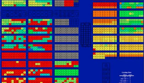
Banner Image Credit: Decay Heat of Fuel Inventory Fukushima Spent Fuel Pool 4, from Nuclear Energy Agency, 2015, Status on Spent Fuel Pools under Loss-of-Colling and Loss-of-Coolant Accident Conditions, Nuclear Safety NEA/CSNI/R(2010)2, May 2015, OECD, p.72, here.
II. SPECIAL REPORT BY ALLISON MACFARLANE
RISKS OF DENSELY PACKED SPENT FUEL POOLS
May 19, 2017
Introduction
Nuclear reactors need spent fuel pools to safely store spent nuclear fuel after discharge from a reactor core. Once discharged, the spent fuel is both thermally and radioactively hot and needs the cooling, shielding, and criticality protection provided by the pool. The pools themselves are similar to very deep swimming pools. In fact, in some reactors divers “swim” in the pools to perform maintenance on them. In some countries, once spent fuel has cooled at least 5 years, it can be transferred to dry casks for passive cooling. Until then, the spent fuel needs the active cooling provided by the circulation of cool water in the pool. As a result, spent fuel pools are necessary equipment at nuclear power reactors.
At the same time, in a number of countries, spent fuel management practices over time have pushed the envelope of pool performance, packing in more and more spent fuel into the same small volume in an effort to deal with large quantities of used fuel. No country has yet developed and operationalized a “final solution” for its high-level nuclear waste, but experts agree that some kind of deep geologic repository will be the solution. Sweden and Finland are furthest along the path to building and eventually opening a mined geologic repository. In the meantime, spent fuel continues to pile up at reactor sites around the world. Some countries largely keep spent fuel in pools at reactors, such as the U.S., some move spent fuel into dry storage, like the U.S. and Germany, some operate away-from-reactor centralized storage sites such as Germany and Sweden, and a few send spent fuel to reprocessing facilities like the U.K. and France.
As spent fuel pools are central to the operation of a nuclear power plant, as large quantities of spent fuel have accumulated in these pools, and given recent safety and security concerns, it is reasonable to address the safety of these facilities. The question addressed here is to what degree and in which circumstances spent fuel pools pose potential threats. I will place this issue in the larger issue of spent fuel management practices in general and discuss spent fuel management practices in a variety of countries.
Technical Background
Spent Fuel Pools
Spent fuel pools in light water reactors are usually located outside of containment, the thick concrete and steel reinforced structure that provides an additional line of defense in preventing radioactive contamination from a reactor accident (Figures 1-4). This is true for all designs except Russian VVER-1000’s, AREVA’s EPR, and the German KONVOI or pre-KONVOI designs, in which the pool is located within the containment (Nuclear Energy Agency, 2015). As a result, for most operational power reactors, in the event of a spent fuel pool accident, radioactivity would be more likely to reach the surrounding environment than with a reactor accident.[1] Additionally, many spent fuel pools are located at or above grade at the site. In the case of General Electric Boiling water reactors of the Mark I and Mark II designs, pools are located at the top floor of the reactor building, often 4 or 5 stories in the air (Figures 1-2).
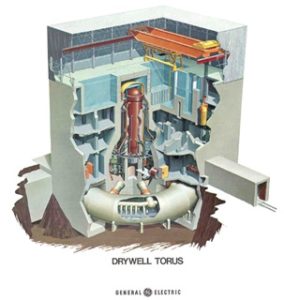
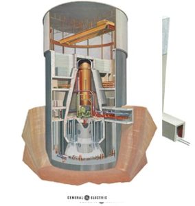
Figures 1 and 2: GE Boiling water reactors. Figure 1 on left is Mark I design, Figure 2 on right is Mark II design. In Mark I, spent fuel pool into upper right of reactor vessel; in Mark II, spent fuel pool is to the upper left of the reactor. Containment in both is the flask-shaped area outside of the red/orange reactor vessel. From NRC, undated.
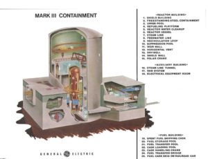
Figure 3: GE Boiling water reactor, Mark III design. Spent fuel pool is to the right of the reactor, number 20, outside the main containment. From NRC, undated.
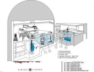
Figure 4: Pressurized water reactor and pool. Pool is to the right in the cartoon – outside the containment. From http://www.nucleartourist.com/images/refuel-bldg.gif.
Pools are made from thick reinforced concrete and have stainless steel liners to prevent leaks. Pool size varies widely between and among reactor designs. In some cases two or more reactors share a single pool. Some reactor sites have more than one storage pool on site. Pool depth is in the 12 m range and fuel is loaded in racks in the lower portion of the pool and has about 7 m of water above it (Nuclear Energy Agency, 2015). Boiling water reactors (BWRs) and pressurized water reactors (PWRs) differ in types of pool racks and method of radiation or reactivity control.
Racks in both PWR and BWR spent fuel pools can be open or closed designs (Figures 5-6). The open frame racks (often the original design) depend on water flow and distance between fuel assemblies in part for criticality control.[2] As space to store more spent fuel was required over the reactor’s lifetime, racks were converted to higher and higher density designs. In PWRs, for instance, they went from a 41-53 cm spacing between the centers of two fuel assemblies in a open frame rack to a 26 cm spacing in a high density rack (Nuclear Energy Agency, 2015). In the high-density PWR and BWR racks, criticality control is done by borated absorber (a metal plate impregnated with boron, an element that captures stray neutrons) between or within the stainless steel rack wall. These high-density racks do not allow for lateral or cross-flow of water between fuel assemblies. Water flow is vertical, convective within each separate fuel assembly cell. PWR pools use borated water in the pools while BWR pools use demineralized water. And unlike PWRs, BWR assemblies are gathered in a metal sheath that directs the water up the channel and provides support to the assemblies and the associated control rods (NRC, undated) (Figure 7).
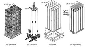
Figure 5: High density storage racks for PWRs. From NEA, 2015.
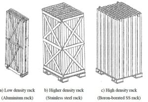
Figure 6: Storage racks for BWRs. From NEA, 2015.
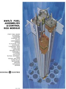
Figure 7: BWR fuel assemblies, showing the metal sheath surrounding the assemblies. From NRC, undated.
Most spent fuel pools are actively cooled with a system of heat exchangers and pumps. The water lines into the pools tend to enter the pools near the top to avoid the potential to inadvertently drain the pool (Nuclear Energy Agency, 2015). These systems are usually attached to backup diesel generators in the case of offsite power loss. Moreover, additional pumps and heat exchangers may be located on site in the case of emergency.
Spent fuel pools usually have instruments that measure water level and temperature and feed this information to the control room operators. Usually, the maximum allowable temperature in spent fuel pools during operation (and especially refueling outages) is 60 °C (Nuclear Energy Agency, 2015). As a result of the Fukushima accident, the US Nuclear Regulatory Commission (NRC) now requires all spent fuel pools in the US to have independent water level controls that can provide water level measurements under station blackout conditions.
Spent Fuel Loading
Spent fuel is loaded into pools after use in the reactor via use of overhead cranes. Fresh fuel is often also stored in pools, awaiting use in reactors. BWRs, VVERs, and German PWRs use transfer canals to move spent fuel from the reactor to the pool, allowing fuel to be moved in a vertical manner. If water is lost from the transfer canal, this can directly affect water level in the pool itself. For PWRs, fuel is transferred horizontally using a transfer tube (Figure 4), which uses a much smaller volume of water and as a result, leaks from the transfer tube won’t affect the spent fuel pool water level very much (Nuclear Energy Agency, 2015).
Many reactor pools maintain space to offload the entire contents of the reactor core (or in the case that one pool is shared by two or more reactors, two or more full cores) in the case of emergency or necessity. The US NRC does not require this of their licensees, and a handful of reactors in the U.S. do not have this capability.
Spent fuel loading patterns may directly affect the potential for an accident in the case of a loss of cooling or coolant accident. Emplacing newly discharged spent fuel assemblies next to each other in one portion of the pool can concentrate heat and pool heat load is highest just after a full core is loaded into the pool, but sometimes it is easier and cheaper to place spent fuel in one location in the pool (in the place where the fresh fuel was stored, for instance).
Some plants, such as the Koeberg nuclear power facility in South Africa use special reinforced racks for freshly discharged spent fuel. Others disperse newly discharged spent fuel into 1 x 4 or 1 x 8 patterns, in which a hot, newly discharged assembly is surrounded by 4 or 8 old cold assemblies (Figure 8). The US NRC, in a recent modeling study, showed the benefits of 1 x 4 and 1 x 8 dispersal patterns over other patterns (NRC, 2014a). The study showed that in the case of the Peach Bottom reactor in Pennsylvania, dispersing hot fuel into a 1 x 8 pattern provided the best pool heat management over surrounding the hot assembly with only 4 cold assemblies or even no assemblies or open rack space. The cold fuel surrounding the hot assembly provides a cold sink for the heat, dissipating the heat in the pool. The 1 x 8 pattern does not decrease time needed in the pool, which is controlled by the decay of short-lived radionuclides.
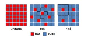
Figure 8: Alternative spent fuel loading patterns for pools. From NEA, 2015.
In the US, for instance, reactors are encouraged to achieve a 1 x 4 pattern, but are not required to do so. US reactors will tend to disperse permanently discharged fuel into at least a 1 x 4 pattern, though this information is not actually tracked by the US NRC. On the other hand, many U.S. PWRs, when discharging a full core, do not do so into a dispersed pattern, opting instead to discharge into a single area of the pool. They will keep the full core in the same location in the pool for the duration of the outage (NRC, 2014b).
Pool Management Practices
Spent fuel pool management practices vary by country. I include a few countries here to illustrate the variety of ways to manage spent fuel in the nuclear fuel cycle.
Canada: Unlike all other countries listed, Canada operates CANDU reactors that use heavy water as a coolant and moderator. As a result, spent fuel cannot go critical in spent fuel pools filled with “light” water, so the spent fuel pool’s function is to maintain thermal and radiation control only. Spent fuel bundles are discharged to spent fuel pools and cooled there for 7-10 years, then transferred to dry storage facilities at reactor sites. In response to the Fukushima accident, Canadian operators have added equipment to reactor sites that can be transported to the pools to add water if needed. They have also installed hydrogen removal equipment to pools that can operate without external electrical power (Canadian Nuclear Safety Commission, 2015).
France: France reprocesses its spent fuel. As a result, it transfers its spent fuel from reactor sites within a few years after discharge to the La Hague reprocessing facility via train. At La Hague, the spent fuel is stored in large cooling pools for another few years before it is reprocessed. Spent MOX spent fuel is also transported back to La Hague after a longer period of cooling in reactor pools, but this fuel is not currently reprocessed (IPFM, 2011).
Germany: Germany reprocessed much of its spent fuel in the facilities in France and the UK until 2005. Since then, it has stored spent fuel at reactor sites and in centralized storage facilities. Most spent fuel is in dry storage at reactor sites (GAO, 2012).
Japan: Japan has managed spent fuel by a variety of methods. Much spent fuel is stored at reactor sites in spent fuel pools, centralized pools at reactors, and in a modest amount of dry storage. Some spent fuel has been shipped to Japan’s Rokkasho reprocessing plant, whose pool is almost at capacity. Other spent fuel was shipped to reprocessing facilities in the United Kingdom and France for reprocessing.
Sweden: Sweden has an off-site interim storage facility, the CLAB facility located in Oskarshamn. CLAB is an underground storage pool facility, 50 m deep, with 2 large storage pools. Spent fuel is transferred to CLAB about 18 months after discharge from reactors. As a result, reactor pools do not maintain large inventories of spent fuel.
United States: Spent fuel remains at reactor sites in the United States. As a result, all spent fuel pools have high-density racks, many of which are almost full. There is no requirement to discharge into a dispersed pattern, although, according to an incomplete survey done by the US NRC, many licensees do use such a pattern.
Past Accidents
Though there have been no major accidents in which spent fuel pools feature, a few smaller-scale accidents or near misses provide interesting benchmarks to understand how such a spent fuel pool accident might progress. The most notable recent near miss was the Fukushima accident that began March 11, 2011, at the Fukushima Dai’ichi plant in Japan. Three boiling water reactor cores eventually melted down, but much concern focused on the condition of unit 4’s spent fuel pool.
Unit 4’s entire core was moved into its spent fuel pool for maintenance work during a routine shutdown in November 2010. At that time, the pool water temperature was 27 °C (Wang et al., 2012). When the accident occurred on March 11, the facility lost all power and entered a state of “station blackout.” At this time unit 4’s spent fuel pool lost active cooling. After a hydrogen explosion in unit 4’s reactor building on March 15, 2011, concerns arose that the spent fuel in the pool had become so hot that the fuel cladding had reacted with steam to form hydrogen. In fact, the source of the hydrogen was unit 3’s reactor, piped in via connections between the two closely spaced buildings. At the time though, many thought unit 4’s spent fuel pool had lost significant water and efforts became focused on adding water to the pool. Since the reactor pool was at the top of the building, now under debris from the explosion, and radiation levels were extremely high, it was inaccessible to humans. So, alternative methods were conceived to add water to the pool. This was done most dramatically by helicopter, which flew over the unit and attempted to drop water into the pool (little of this water actually reached its target). On March 20, cranes to the pool lifted hoses from Japanese Defense Forces fire trucks and water was sprayed into the pool. By June 16, water was added to the pool with a temporary injection facility, providing a more stable form of water addition (Wang et al. 2012).
The fuel in unit 4’s pool was loaded into high-density racks and the fuel discharged from the entire core was inserted into positions adjacent to each other. Measured temperatures show a marked increase after the accident – to 84 °C on March 14 to 90°C on April 12 (30 °C over the desired maximum pool temperature). By mid June, water temperatures had dropped to about 70 °C (Wang et al., 2012). No water level readings were available until mid April, when measurements show water levels of 1.8 – 2.0 m above the top of the spent fuel (Wang et al., 2012). If water level were to drop below the top of spent fuel, it could ignite and catch fire, releasing radioactivity. Modeling done by Wang and others (2012) suggests that water levels began to drop in the pool beginning around March 13 and dropped about 0.7 m/day, based on local meteorological conditions and estimated evaporation rates. If water addition had not begun by March 20, at that predicted rate of decrease, the fuel would have been uncovered by March 23, just under two weeks from loss of active cooling. This suggests that loss of cooling events at spent fuel pools are not dire emergencies that need to be addressed within hours, but slower-moving events that do require backup systems and a variety of alternative approaches to resolve.
Another spent fuel pool accident sheds light on how fuel can be damaged in a pool. The Paks nuclear power plant in Hungary experienced an INES level 3 accident on April 10, 2003 in the spent fuel pool of the unit 2 reactor. The Paks reactors are VVER-440 designs, and the fuel develops magnetite corrosion during use. The corrosion – called crud – is removed from the fuel assemblies, 30 at a time, in a tank placed at the bottom of the spent fuel pool (Figure 9). On April 10, 2003, after the assemblies were cleaned, they were not removed from the tank because the crane used to lift them was being used elsewhere. As a result, they stayed in the cleaning tank. The fuel was cooled by a pump with a low flow rate, which allowed the fuel to heat up and form steam. The steam pushed most of the water out of the cleaning tank and the fuel assemblies then, over a matter of hours, heated to over 1000 °C and were severely damaged (IAEA, 2009). The spent fuel heated so quickly in part because the tank it was kept in was small, and the water, once turned to steam, was forced out of the tank. Once the tank was discovered, it was opened, and cool pool water rushed in, quenching the overheated fuel rods, fracturing them, and releasing noble gases (the non-reactive gases like helium, neon, argon, krypton, xenon, radon) into the atmosphere around the plant. Volatile and non-volatile radionuclides, like cesium-137, were retained in the pool water and collected on filters in the pool (Hozer et al, 2009). Fission product noble gases released were xenon-133 (1013 Bq released per 10 min.), krypton-85 (1012 Bq released per 10 min.), and iodine-131 (109 Bq released per 10 min.) with 99% of the total release occurring in the first 24 hours of the accident (Hozer, 2009). These products didn’t stay in the pool because of their low solubility in water, but instead went out of the stack and into the surrounding atmosphere (Hozer, 2009).
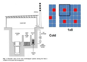
Figure 9: Diagram of the Paks 2 spent fuel storage and treatment systems. From Hozer, 2009.
The Paks 2 accident suggests that even in the event of a loss of cooling or coolant accident in which spent fuel is not uncovered but damaged, some amount of radioactive release can occur. Since many spent fuel pools contain hundreds of assemblies, this release of noble gases could be significant.
Threats
Spent fuel pools must be designed to defend against three main potential threats: criticality accidents, loss of cooling accidents, and loss of coolant accidents. As explained above, criticality mitigation has become more of an issue with the rise of high-density racks. Open frame racks load fuel assemblies far enough apart so that criticality is not an issue. High density racks place fuel assemblies close enough so that neutron absorbers must be added to the rack material to prevent criticality. Some neutron absorbing materials used previously in the U.S., such as boraflex, have degraded in the spent fuel pools due to radiation damage and have caused concern about the ability to maintain reactivity control in spent fuel pools. Some pools use borated water to aid in controlling criticality. In the case of a loss of boron input and circulation in the pool, criticality may also be compromised.
Loss of cooling accidents, in which the cooling function is lost, and loss of coolant accidents, in which pool water or coolant is lost through leakage or sloshing both can pose significant problems. Spent fuel pools at “mature” power reactors pose a potential threat because of the possibility of radionuclide contamination in the event of a loss of cooling or coolant accident that involves a self-propagating zirconium cladding fire. Pools contain much higher “source terms” than reactor cores simply because, at plants that have been operating for many years, they can contain many reactor cores’ worth of spent fuel. The source term for a high density pool like that of the Peach Bottom reactor in the U.S. ranges from 40 to 140 million curies of cesium-137. For perspective, the amount released by the Fukushima accident was between 0.2 to 0.8 million curies of cesium-137 (Macfarlane, 2014). The US NRC’s recent modeling of a fire at the Peach Bottom pool suggested that in a high density configuration with no mitigation, the accident would affect 9,400 square miles of land, displacing over 4 million people, and result in a collective dose of 350,000 person-sieverts (NRC, 2014a).
Most studies, including the ones mentioned in this report, analyze a total loss of coolant. Few studies examine a partial loss of coolant in which there is a slow leak and the fuel becomes uncovered but the pool does not drain. In this case, fuel assemblies may not be able to take advantage of convective cooling up the cells in the high-density racks. An open-frame rack may provide cooling of fuel through convection in the case of partial drain down (Alvarez et al, 2003).
Loss of coolant accidents can result from a few scenarios: massive earthquake, cask drop, accidental plane crash, or terrorism. When analyzed by the US NRC, all events precursor events were found to have a very low probability of occurrence (see for example, NRC 2001, 2014a), even though the consequences of an accident would be high. Spent fuel pools are built robustly, and in seismically active areas, are reinforced to withstand shaking from earthquakes. Of course, they are only built to withstand the expected earthquakes and have additional margin added, and sometimes, as happened in Fukushima in 2011, at the North Anna plant in Virginia, US in 2011, and at the Kashiwaszaki-Kariwa plant in Japan in 2007, seismic building standards are exceeded by Mother Nature.
Loss of coolant accidents from cask drops need some explanation. Spent fuel is often transferred via a canister or small cask out of the pool for either dry storage or storage elsewhere (for instance, at a reprocessing facility). This is done by loading the spent fuel into a cask under water in the pool. Water is later drained and the cask removed from the pool via crane. Damage to the pool’s integrity may result were the cask to drop into the pool while suspended by the crane. Casks can be heavy and if dropped from a height may exert significant force on the pool bottom or walls.
Inadvertent or deliberate plane crash could also damage spent fuel pools. Most spent fuel pools lie outside of containment and do not have the additional protection provided by such a structure. The US NRC performed a classified study of plane crashes into spent fuel pools after the attacks of September 11, 2001. They also completed classified studies of terrorist attack with high-energy weapons or explosive charges. The National Academy of Sciences (2006) reviewed these studies and, “Concluded that there are some scenarios that could lead to the partial failure of the spent fuel pool wall, thereby resulting in the partial or complete loss of pool coolant. A zirconium cladding fire could result if timely mitigative actions to cool the fuel were not taken.” (National Research Council, 2006, p. 49). A recent National Academies report (National Academy of Sciences, 2016) reviewed these previous findings and noted that there are additional threats such as unmanned aerial vehicles and cyberattacks that could provide additional pathways to an accident scenario.
Security at nuclear power plants is not governed by any international standards, unlike safety, for which the International Atomic Energy Agency, among others, sets example standards for countries to consider. In the U.S., security at nuclear power plants is governed by regulations set by the NRC, which has responsibility for ensuring safety and security at reactors. As a result, nuclear power plants are well-guarded facilities[3] that have considered and practiced scenarios of terrorist attack that affects the operation of the reactor and associated safety systems. In other countries, security is provided by the local police force. Recently, a number of plant breaches by anti-nuclear activists in Sweden and France have made clear some vulnerabilities at these plants.
Loss of cooling accidents can result from loss of offsite electric power and backup diesel generators, a situation referred to as station blackout, similar to what Fukushima Dai’ichi suffered during the March 2011 accident. Cooling loss can also occur when a pump fails or is inadequate, so coolant is no longer circulated, as happened in the Paks 2 accident.
Loss of cooling can also occur from lack of heat removal – especially in the case of higher heat loads in the pool. Higher heat loads might result from higher fuel burnup or the presence of spent MOX fuel. Burnup refers to the number of atoms that have fissioned in the fuel or the energy released by the fuel and is expressed in mega (or giga-) watt – days per metric tonne heavy metal. In the 1970s and 1980s, a typical burnup for light water reactors were in the 33-40 MWd/MTHM range. Now burnup averages 50 MWd/MTHM (Xu et al., 2005). Some in the nuclear industry are pushing to use even higher burnup, in the 70 MWd/MTHM range in the near future. Higher burnup results in less spent fuel to manage and squeezes more energy out of a single fuel rod, potentially allowing reactor operators to extend times between outages and therefore run a leaner operation. Higher burnup requires higher enrichment of fresh fuel in uranium-235. To achieve a burnup of 50 MWd/MTHM, enrichments of 4.5% U-235 are needed; to achieve a burnup of 70 MWd/MTHM, enrichments of 6.3 % are needed (Xu et al, 2005).
Higher burnup fuel generates spent fuels that produce more heat. For instance, according to models of PWR spent fuel discharged 10 days previously, a burnup of 35 GWd/MTHM generates 5.5 x 10⁴ W/MTHM versus 9 x 10⁴ W/MTHM for a burnup of 50 GWd/MTHM (ORNL, 2011). As a result, as more high-burnup spent fuel assemblies are added to a pool, overall heat loads will increase in the pool and will decrease more slowly over time. These increased heat loads may be accompanied by a reduction in the absolute number of spent fuel assemblies, but this benefit has yet to be realized.
MOX or mixed oxide fuel poses a similar problem. MOX is formed by mixing plutonium oxide with uranium oxide to fuel reactors. Currently, France, Germany, Switzerland, and Japan are among the countries using MOX fuel as well as uranium oxide fuel. MOX spent fuel, because of its initial plutonium content, has higher decay heat than its uranium dioxide equivalent. For instance, for models of PWR spent fuel with a 35 GWd/MTHM burnup, 10,000 days after discharge, uranium oxide fuel produces 8 x 10² W/MTHM versus 2.4 x 10³ W/MTHM for MOX spent fuel, almost 50% more heat (ORNL, 2011). Spent fuel pools have to be able to manage this additional heat and have necessary backup equipment to handle the load in case of accident.
Mitigation
A number of measures can be taken to avoid or mitigate potential accidents. First, though, it is important to understand which factors heighten the potential for loss of cooling or coolant accidents. The amount of spent fuel in the pool, the time since discharge of that spent fuel, the type of racks in the pool, and the loading pattern of spent fuel in the pool are all factors that can affect the potential for accident in the case of loss of cooling or coolant. A number of these factors are interrelated.
Reducing the amount of spent fuel in cooling pools, in particular moving all fuel older than 5 years from discharge into dry storage, suggested by Alvarez and others (2003) as a strategy to deal with the potential for accidents, would reduce the source term by a factor of four and would reduce the heat load in the pool. Reducing the amount of spent fuel in the pool would also allow for the use of open frame racks, which, in the case of loss of coolant, allow for air cooling of spent fuel rods. The high-density racks in use today in many pools are closed-cell racks that allow for little air access and depend largely on vertical water circulation to provide cooling.
Transfer of spent fuel from the pool to dry storage is not without costs. Transfer capability must exist[4] and casks and cask storage areas – either concrete pads or buildings – must be available as well. Transferring large quantities of spent fuel will increase the potential for cask drop – a possible initiating event for a loss of coolant accident. Moreover, workers transferring the spent fuel would be exposed to more radiation (GAO, 2012). Finally, of course, are the actual costs of dry storage – the facilities, the casks, and the security and monitoring required once it is in place.
The period of highest vulnerability during the operation of a spent fuel pool is shortly after spent fuel is discharged into the pool. The recent NRC models (NRC, 2014a) suggest that for the first 3-4 months after discharge from the reactor, spent fuel can ignite within 72 hours, if the fuel is uncovered and no mitigative measures are taken. Over the 20-year life of a reactor, these 3-4 month blocks add up to a significant period of time – between one and five years (Macfarlane, 2014). This period of vulnerability is exacerbated if recently discharged spent fuel is placed adjacent cells, instead of using a loading pattern that can absorb some heat, like the 1 x 4 or better, the 1 x 8 pattern. Therefore, it is important to require nuclear power plant operators to discharge spent fuel – and especially full cores – into a dispersed loading pattern in the pool, such as the 1 x 4 or 1 x 8 patterns.
Other mitigative measures include ensuring the ability to add water in the case of loss of coolant. This can be done with fixed and transportable equipment. Examples of fixed equipment are water cannons mounted near the pool and hose bibs attached to building walls near the pool. Transportable equipment can be similar to that used in the Fukushima accident – hose trucks to spray water into the pool. Additional pumps, heat exchangers, piping and wiring can also be located at the reactor site in case of cooling or coolant failure. Connections to on-site diesel generators are essential in the case of off-site power loss.
In the aftermath of the Fukushima accident a number of regulators in various countries have required the addition of equipment (both fixed and transportable) to ensure safety of the spent fuel pools. Some have gone beyond adding water addition and cooling equipment to requiring hydrogen mitigation equipment in the case of hydrogen generation from the oxidation of the zirconium cladding on spent fuel. Build up of hydrogen can result in massive explosions, as occurred in Fukushima.
Unknowns
By their nature, loss of coolant or cooling accidents at spent fuel pools are low probability, high consequence events. These events are generally difficult for society to deal with: as they may never occur, the need for investment in prevention is often questioned. At the same time, were an accident to occur, with little or no attempted prevention, the consequences could be dire, with potentially millions of people affected, and blame laid squarely on the nuclear industry.
All is not currently understood about the progression of an accident in a spent fuel pool. The ability of open-frame racks to mitigate an accident has not been investigated in detail, for instance. In its recent modeling of a spent fuel pool accident (NRC, 2014a), the NRC used two main scenarios, both using high density-type closed-cell racks: one with the cells completely full, and one with the cells partially full. They did not model the response of fuel assemblies in open-frame racks that allow significant water and air circulation.
Another area ripe for investigation is potential alternative loading patterns of recently discharged spent fuel into pools. Recent NRC analysis (2014a) suggests the advantages of using a 1 x 8 pattern where one hot fuel assembly is surrounded by 8 cold ones that provide a cold sink. The question remains whether there are other loading patterns that may be even more helpful in reducing risk of spent fuel fires in pools.
Loss of coolant accidents should be examined more closely, in particular the case where enough of the coolant is lost to uncover the spent fuel but not completely drain the pool. This situation impedes air-cooling of fuel because water blocks the circulation of air around the entire fuel assembly. As a result it is important to understand how much time it would take for spent fuel to heat up to ignition temperatures.
Over the longer term new more accident-tolerant fuels should be investigated, including cladding materials that would resist reactions with steam that produce hydrogen. Spent fuel management can be made safer, but first it is necessary to understand the range of options to promote safe spent fuel pool storage.
Conclusions
Spent fuel pools are a necessary part of nuclear reactor operation. They very simply provide the necessary thermal cooling, criticality control, and radiation protection needed for spent nuclear fuel. But they are not without risk. I would argue that the back end of the fuel cycle, especially at reactors, has not received the attention to safety and management it needs. Management of spent fuel after discharge from the reactor requires careful thought and safety analysis. Surprisingly, regulators in some countries have taken a laissez-faire attitude to the back end of the fuel cycle at reactors. For instance, the U.S. NRC does not require its licensees to report quantities of spent fuel, spent fuel pool loading patterns, loading patterns directly after discharge, whether full-core offload is maintained in the pool, and other pertinent information.
With the back end of the fuel cycle there are straightforward options for managing spent fuel to ensure safety. Spent fuel pools at reactors could be used as in Sweden and France – for recently discharged fuel, which is moved offsite quickly. They can also be used to hold fuel less than 5 years old. After 5 years of cooling, spent fuel can be transferred to passive dry storage. Spent fuel can be discharged into rack loading patterns that ensure the safest configuration in the case of loss of cooling or coolant accidents. Finally, open frame racks can be used to maximize the potential for air circulation in a loss of coolant accident.
III. REFERENCES AND ENDNOTES
Alvarez and others (2003) Reducing the hazards from stored spent power-reactor fuel in the United States, Science and Global Security, 11, p. 1-51.
Canadian Nuclear Safety Commission (2015) High Level Radioactive Waste, from CNSC’s website: http://nuclearsafety.gc.ca/eng/waste/high-level-waste/index.cfm#Wet, modified: 2/23/2015, accessed 9/4/2015.
Entergy (2012) Entergy to Begin Removing Spent Fuel from Unit 3 Spent Fuel Pool, September 14, 2012, http://www.entergy.com/news_room/newsrelease.aspx?NR_ID=2549.
Government Accountability Office (2012) Spent Nuclear Fuel: Accumulating Quantities at Commercial Reactors Present Storage and Other Challenges, GAO-12-797, August, 2012.
Hozer and others (2009) Activity release from damaged fuel during the Paks-2 cleaning tank incident in the spent fuel storage pool, Journal of Nuclear Materials, 392, pp. 90-94.
International Atomic Energy Agency (2009) OECD-IAEA Paks Fuel Project Final Report, Vienna.
International Panel on Fissile Materials (2011) Managing Spent Fuel from Nuclear Power Reactors: Experience and Lessons from Around the World, September, 2011.
Macfarlane (2014) Chairman Macfarlane’s Comments on COMSECY-13-0030 Staff Evaluation and Recommendation for Japan Lessons-Learned Tier 3 Issue on Expedited Transfer of Spent Fuel, April 8, 2014.
National Research Council, 2006, Safety and Security of Commercial Spent Nuclear Fuel: Public Report, Washington, DC: National Academies Press.
National Research Council, 2016, Lessons Learned from the Fukushima Accidentfor Improving Safety and Security of Nuclear Plants, Phase 2, Washington, DC: National Academies Press.
Nuclear Energy Agency, 2015, Status on Spent Fuel Pools under Loss-of-Colling and Loss-of-Coolant Accident Conditions, Nuclear Safety NEA/CSNI/R(2010)2, May 2015, OECD.
Nuclear Regulatory Commission (undated) Boiling Water Reactor Systems, Reactor Concepts Manual, USNRC Technical Training Center, https://www.nrc.gov/reading-rm/basic-ref/students/for-educators/03.pdf
Nuclear Regulatory Commission (2001) Technical Study of Spent Fuel Pool Accident Risk at Decommissioning Nuclear Power Plants, NUREG-1738.
Nuclear Regulatory Commission (2014a) Consequence Study of a Beyond-Design-Basis Earthquake Affecting the Spent Fuel Pool for a US Mark I Boiling Water Reactor, NUREG-2161.
Nuclear Regulatory Commission (2014b) Policy Issue Information: SECY-14-0136, Response to Commission Direction on Spent Fuel Pool Limited Term Operational Vulnerabilities, November 26, 2014.
Oak Ridge National Laboratory (2011) Decay Heat Calculations for PWR and BWR Assemblies Fueled with Uranium and Plutonium Mixed Oxide Fuel Using Scale, ORNL/TM-2011/290, September, 2011.
Wang, and others (2012) Study of Fukushima Daiichi nuclear power station unit 4 spent-fuel pool, Nuclear Technology, 180, pp. 205-215.
Xu, M. Kazimi, and M Driscoll (2005) Impact of high burnup on PWR spent fuel characteristics, Nuclear Science and Engineering, 151, pp. 261-273.
ENDNOTES
[1] In the Three Mile Island accident in 1979, even though the reactor suffered a partial meltdown, radioactivity generated did not contaminate the surrounding area because the containment operated as planned and contained the radionuclides. Conversely, the Chernobyl reactor that melted down in 1986 did not have containment and as a result contaminated a huge swath of land.
[2] PWR spent fuel pools also use borated water for criticality control (Nuclear Energy Agency, 2015).
[3] At some US nuclear power plants, the guard force makes up one third of the entire workforce at the plant.
[4] Transferring spent fuel from the pool to dry storage requires a crane strong enough to lift the loaded cask, space in the pool to emplace the cask, facilities at the reactor site to decontaminate and seal the cask, a specially-designed transfer vehicle to move the filled cask to the storage site. As a case in point, the Indian Point power plant in New York did not have the capability until 3 years ago to remove spent fuel from unit 3’s pool because it could not accommodate the large crane needed to lift loaded casks. To resolve the problem they added a smaller crane to lift a small, water-filled transfer cask with 12 fuel assemblies. This transfer cask is brought to unit 2’s spent fuel pool where a full-size storage cask can be loaded (Entergy, 2012).
IV. NAUTILUS INVITES YOUR RESPONSE
The Nautilus Asia Peace and Security Network invites your responses to this report. Please send responses to: nautilus@nautilus.org. Responses will be considered for redistribution to the network only if they include the author’s name, affiliation, and explicit consent.


