")
THE ANTENNAS OF PINE GAP
Desmond Ball, Bill Robinson and Richard Tanter
22 February 2016
Full report available here [7 MB]. Online-optimized version for faster download here [ 2.6 MB].
I. Introduction
Antennas are the most readily available and visible evidence of the existence, character, and size of signals intelligence facilities that operate or monitor space systems. Coupled with data on the timing of developments in US geosynchronous satellite programs, the timing of antenna installation now permits, for the first time, identification of the role and function of almost all antennas at Pine Gap. Documenting the development of the antenna systems of Pine Gap provides visual evidence of the profound changes in the base’s operations and its missions: a subject of political controversy in Australia for half a century. The antennas of Pine Gap are a powerful political symbol in Australia, representing either promise of enduring alliance protection or loss of national autonomy and nuclear threat to different audiences.
Since 1967, at least 46 antenna systems have been installed at Pine Gap, including 23 parabolic dish antennas covered by protective radomes and 23 uncovered antennas of assorted types. Four of those in radomes were subsequently dismantled (although three were replaced by other systems in radomes); nine without radomes also have been dismantled. Of the 33 antenna systems at the facility as of February 2016, 19 were in radomes and 14 were uncovered.
Authors
Desmond Ball is Emeritus Professor at the Australian National University (ANU). He was a Special Professor at the ANU’s Strategic and Defence Studies Centre from 1987 to 2013, and he served as Head of the Centre from 1984 to 1991.
Bill Robinson writes the blog Lux Ex Umbra, which focuses on Canadian signals intelligence activities. He has been an active student of signals intelligence matters since the mid-1980s, and from 1986 to 2001 was on the staff of the Canadian peace research organization Project Ploughshares.
Richard Tanter is Senior Research Associate at the Nautilus Institute and Honorary Professor in the School of Political and Social Sciences at the University of Melbourne.
Cover photograph by Source: Kristian Laemmle-Ruff, (Attribution – NonCommercial CC BY-NC).
Images in this paper by Kristian Laemmle-Ruff and by Felicity Ruby may be used for non-commercial purposes, subject to attribution and other conditions under Creative Commons Licence Attribution 2.0 Generic (CC BY 2.0): see http://creativecommons.org/licenses/by/2.0/.
See Kristian Laemmle-Ruff Photography at http://www.kristianlaemmleruff.com/, and Felicity Ruby – The Fourth Eye, at http://FelicityRuby.com/.
Larger versions of all images will be available shortly on the main Pine Gap page on the Nautilus Institute Australian Defence Facilities website, at https://nautilus.org/publications/books/australian-forces-abroad/defence-facilities/, currently under reconstruction.
Very large file size versions of Laemmle-Ruff’s images are available through his website. Media requests for reproduction rights should be directed to that website. Felicity Ruby’s photographs are available through her website.
Note that the small spheres across the upper part of the cover image are lens flares, an artifact of the camera pointing directly at light sources at night.
Acknowledgements
We acknowledge the traditional owners and elders of the land on which the Pine Gap facility is located, and wish to express our gratitude for the kind assistance given to this project at an important point. We also thank Rosalie Schultz for assistance in fieldwork. We are deeply grateful to Felicity Ruby and Kristian Laemmle-Ruff, who very generously gave us permission to reproduce their photographs of Pine Gap. Luke Hambly from the Coral Bell School of Asia Pacific Affairs at the Australian National University kindly prepared the Figure 2. Philip Dorling kindly provided a government photograph to us. We are grateful to Rebecca Pollack at Nautilus Institute in Berkeley for patient and expert help with the preparation of this and other publications in this series.
The views expressed in this report do not necessarily reflect the official policy or position of the Nautilus Institute. Readers should note that Nautilus seeks a diversity of views and opinions on significant topics in order to identify common ground.
II. Special Report by Desmond Ball, Bill Robinson and Richard Tanter
The Antennas of Pine Gap
Report
Full report available here [7 MB]. Online-optimized version for faster download here [ 2.6 MB].
Contents
- Introduction……………………………………………………………………………………………………………. 10
- Antenna identification system……………………………………………………………………………………. 11
- The first communications systems………………………………………………………………………………. 22
- The first Rhyolite antennas and radomes……………………………………………………………………… 23
- High frequency (HF) radio communications…………………………………………………………………… 28
- The SCT-35 and SCT-8 DSCS antenna systems………………………………………………………………… 31
- The Aquacade satellites…………………………………………………………………………………………….. 33
- The early Orion radomes…………………………………………………………………………………………… 35
- Two new Australian radomes in 1990-91………………………………………………………………………. 48
- May 1989, September 1994 and May 2002 stock-takes…………………………………………………… 50
- DSP/SBIRS antenna systems…………………………………………………………………………………….. 52
- The Space Tracking and Surveillance System (STSS) antenna systems ………………………………. 60
- Foreign satellite/communications satellite (FORNSAT/COMSAT) interception antenna systems 61
- Antennas without radomes, 1999-2005………………………………………………………………………. 63
- The UHF Helical antenna systems………………………………………………………………………………. 68
- Antennas without radomes, 2005-2015………………………………………………………………………. 69
- The Torus multi-beam antenna system………………………………………………………………………. 71
- Orion-7 radome in 2010-11……………………………………………………………………………………….. 75
- Conclusion …………………………………………………………………………………………………………… 77
1. Introduction: Antennas of Pine Gap
Antennas are the most readily available and visible evidence of the existence, character, and size of signals intelligence facilities that operate or monitor space systems. Coupled with data on the timing of developments in US geosynchronous satellite programs, the timing of antenna installation now permits, for the first time, identification of the role and function of almost all antennas at Pine Gap. Documenting the development of the antenna systems of Pine Gap provides visual evidence of the profound changes in the base’s operations and its missions: a subject of political controversy in Australia for half a century. The antennas of Pine Gap are a powerful political symbol in Australia, representing either promise of enduring alliance protection or loss of national autonomy and nuclear threat to different audiences.
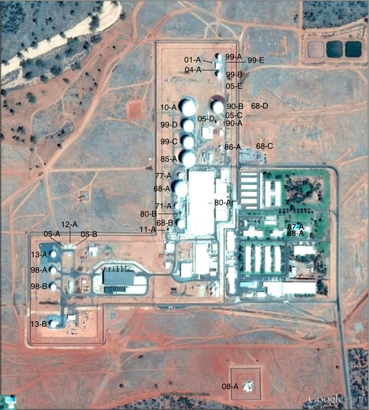
Since 1967, at least 46 antenna systems have been installed at Pine Gap, including 23 parabolic dish antennas covered by protective radomes and 23 uncovered antennas of assorted types. (See Table 1.) Four of those in radomes were subsequently dismantled (although three were replaced by other systems in radomes); nine without radomes also have been dismantled. Hence, of the 33 antenna systems at the facility as of February 2016, 19 were in radomes and 14 were uncovered (see Table 1 and Figures 1 and 2).
Most of these are still concerned with Pine Gap’s core functions relating to geosynchronous SIGINT satellites – controlling the satellites, maintaining the boresights of the intercept antennas on the satellites, downlinking the intercepted data from the satellites, and sending both raw and processed data to an increasing number of users. (See Figure 3.)
Six of the satellite terminals now at Pine Gap (four in radomes and two unshielded) belong to the DSP/SBIRS Relay Ground Station (RGS), which relays early warning and missile tracking data down-linked from Defense Support Program (DSP) and Space Based Infrared System (SBIRS) satellites. Another three radomes are probably associated with the US Missile Defense Agency’s Space Tracking and Surveillance System (STSS) developmental satellites.
Pine Gap evidently acquired a foreign satellite/communication satellite (FORNSAT/COMSAT) interception mission around 1999-2000, with the arrival of elements of the National Security Agency’s (NSA’s) Service Cryptologic Agencies (SCAs) at the end of the 1990s. Two very suitable 23-metre dishes were installed inside 30-metre radomes in 1999-2000. A Torus multi-beam antenna for interception of secondary satellite communications, and capable of receiving in the order of a thousand communications channels simultaneously was installed in 2008.[1]
Some of the antenna systems were installed to facilitate Australian participation in Pine Gap’s activities, including two satellite dishes/radomes built in 1990-91 to provide the Defence Signals Directorate (DSD) with direct access to SIGINT collected at the station.
2. Antenna identification system
One aim of this research is to identify all antenna systems installed at Pine Gap since 1967, with a view to then understand their characteristics and likely roles. There is no publicly available information about the system by which the US government identifies antennas and other elements of Pine Gap infrastructure. Over a number of years, the authors have used different systems of antenna identification, each mainly based on the numerical order in which antennas were installed. As the number of antennas known to have been installed grew, and as more accurate information about the date of antenna installation was established (and on occasion revised more than once), it became clear that the identification of a particular antenna in a straightforward chronological system may need to be revised, sometimes more than once, leading to confusion. In Table 1, column 2, the authors introduce a year-based identification system.
The antennas are listed in chronological order, with some allowance for uncertainty in particular cases. The antenna identification number in column 2 is based on the year that the antenna was installed (see column 6), with a letter suffix further identifying it within the group installed that year. The first antenna listed, 67-A, was built in 1967, and it was the first (and only) antenna built that year. The second antenna listed, 68-A, was one of four installed in the following year. In cases of uncertainty, the best estimate is noted with a question mark. When an antennna is known to have been installed at some point during a specific period, the indentification number is derived from the earliest possible year of construction in that range – e.g. antenna 86-A is known to have been installed between 1986 and 1988.
Figure 1. Antenna systems at Pine Gap, Google Earth imagery, 6 November 2015
|
Authors’
|
Size (ft.) antenna/
|
Size (m.) antenna/
|
Coordinates |
Built |
Comments |
|
| 1 | 67-A | ? | 1967 | No radome. UHF Yagi antenna.Located on the roof of the Operations Building. Provided link to the Alice Springs Telecom tower.Dismantled. |
||
| 2 | 68-A | 85/125 | 26/38 | -23.798403°,
133.736261° |
1968 | Radome replaced in 1977. |
| 3 | 68-B | ?/67 | ?/20 | -23.799296°,
133.736276° |
1968 | Radome replaced in 1977. |
| 4 | 68-C | ? | -23.797437°,
133.738290° |
1968 | No radome.
HF radio transmitting antenna. |
|
| 5 | 68-D | ? | -23.796319°,
133.738033° |
1968 | No radome.
HF radio receiving antenna. Tower is about 15 metres high. |
|
| 6 | 69-A | ?/60 | ?/18 | -23.798040°,
133.737430° |
1969 | Radome.
‘Research’ dish. Dismantled in 1973. Site occupied by 73-A in 1973. |
| 7 | 69-B | ?/15 | ?/5 | -23.798814°,
133.736224° |
1969 | Radome.
Dismantled in 1980. Upgraded to 80-B in 1980. |
| 8 | 69-C | ? | ? | ? | 1969 | No radome.
Dismantled. |
| 9 | 71-A | ?/50 | ?/15 | -23.798849°,
133.736185° |
1971 | Radome. |
| 10 | 73-A | 35/60 | 11/18 | -23.798040°,
133.737430° |
1973 | Radome.
SCT-35 DSCS dish. Dismantled in 1991-1994. Located at site previously occupied by 69-A. Operations Building addition built on site c.1998. |
| 11 | 77-A | ?/50 | ?/15 | -23.798071°,
133.736247° |
1977 | Radome. |
| 12 | 80-A | 8/15 | 2/5 | -23.798773°,
133.737046° |
1980 | Radome.
SCT-8 DSCS dish. Installed on roof of Operations Building. |
| 13 | 80-B | ?/25 | ?/8 | -23.799051°,
133.736280° |
1980 | Radome.
‘Upgrade’ in size of 69-B. |
| 14 | 84-A | ? | ? | ? | 1984 | No radome. Large HF LPA.Dismantled by 1997. |
| 15 | 85-A | 95-100/125 | 29-31/38 | -23.797614°,
133.736466° |
1985 | Radome. Reportedly associated with the Orion-1 (Magnum-1) satellite. |
| 16 | 86-A | 25/ | 8/ | -23.797372°,
133.737366° |
1986-1988 | No radome. |
| 17 | 87-A | 18/ | 5/ | -23.799438°,
133.739077° |
1986-1988 | No radome.
South of tennis court. TV reception? |
| 18 | 88-A | 18/ | 5/ | -23.799505°,
133.739129° |
1986-1988 | No radome.
South of tennis court. TV reception? |
| 19 | 88-B | ? | ? | 1986-1988 | No radome. Dismantled. |
|
| 20 | 89-A | ?/22 | ?/7 | -23.799415°,
133.735998° |
1989 | Radome.
Dismantled. Site later occupied by 11-A. |
| 21 | 90-A | ?/30 | ?/9 | -23.796753°,
133.737278° |
1990-1991 | Radome.
One of pair announced in August 1990. Communications. |
| 22 | 90-B | ?/100 | ?/30 | -23.796316°,
133.737278° |
1990-1991 | Radome.
One of pair announced in August 1990. Communications. |
| 23 | 98-A | 33/52 | 10/16 | -23.800425°,
33.732769° |
1998 | Radome. DSP/SBIRS. |
| 24 | 98-B | 33/52 | 10/16 | -23.800811°,
133.732769° |
1998 | Radome. DSP/SBIRS. |
| 25 | 99-A | 66/ | 20/ | -23.795116°,
133.737281° |
1999? | No radome.
Communications re DSP/SBIRS. |
| 26 | 99-B | 66/ | 20/ | -23.795576°,
133.737288° |
1999? | No radome.
Communications re DSP/SBIRS. |
| 27 | 99-C | 72/100 | 22/30.5 | -23.797218°,
133.736466° |
1999 | Radome.
One of pair built just N of 85-A. FORNSAT/COMSAT collection role. |
| 28 | 99-D | 72/100 | 22/30.5 | -23.796774°,
133.736462° |
1999 | Radome.
One of pair built just N of 85-A. |
| 29 | 99-E | 3/ | -23.795257°,
133.737448° |
Before 9.2004 | No radome.
Present in 1999 DoD photo. |
|
| 30 | 01-A | 6/ | -23.795250°,
133.737121° |
Before 9.2004 | No radome. | |
| 31 | 01-B | 2.5/ | -23.795135°,
133.736749° |
Before 9.2004 | No radome.
Present ?/2004-2012/13. Dismantled in 2013. |
|
| 32 | 01-C[2] | No radome.
Dismantled. Not present in September 2004. |
||||
| 33 | 03-A | 16/ | 5/ | -23.799829°,
133.732699° |
2003-2004? | No radome.
RGS area. Dismantled in 2011-2012. |
| 34 | 03-B | 16/ | 5/ | -23.800025°,
133.732712° |
2003-2004? | No radome.
RGS area. Dismantled in 2011-2012. |
| 35 | 04-A | western mast:
-23.795454°, 133.737057°
eastern mast: -23.795459°, 133.737176° |
8.2005 – 10.2009 | Helical antenna array.
Located on southwest and southeast corners of the building between 99-A and 99-B. Two small single helical antennas installed by September 2004. Present in Google Earth imagery dated 8 September 2004. |
||
| 36 | 05-A | ?/17 | ?/5 | -23.799853°,
133.733103° |
2005-2008? | Radome.
STSS-related? |
| 37 | 05-B | ?/17 | ?/5 | -23.799856°,
133.733361° |
2005-2008? | Radome.
STSS-related? |
| 38 | 05-C | 4/ | -23.796584°,
133.737283° |
2005-2009 | No radome.
Built in 2005-2009. |
|
| 39 | 05-D | 4/ | -23.796594°,
133.737190° |
2005-2009 | No radome.
Built in 2005-2009. |
|
| 40 | 05-E
|
-23.795813°, 133.737426° |
2005-2009 | Helical antenna array.
Located south of 99-B. Four masts with twin helicals installed between 2005 and 2009. Not present in Google Earth imagery dated 11 August 2005. Present in TerraServer imagery in October 2009. |
||
| 41 | 08-A | 75?/ | 23?/ | -23.803366°,
133.738043° |
2008 | Torus multiple-beam antenna.
FORNSAT/COMSAT collection role. |
| 42 | 10-A | 95-100?/125 | 29-31?/38 | -23.796265°,
133.736433° |
2010
|
Radome. Probably associated with the Orion-7 satellite. |
| 43 | 11-A | 40/ | 12/ | -23.799440°,
133.735973° |
2011-2012 | No radome.
Installed on the site previously occupied by 89-A. |
| 44 | 12-A | ?/17 | ?/5 | -23.799822°,
133.733232° |
2012 | Radome.
STSS-related? |
| 45 | 13-A | 33?/52? | 10/16 | -23.800003°,
133.732771° |
2013 | Radome.
DSP/SBIRS. |
| 46 | 13-B | ?/ca. 60? | ?/18 | -23.801743°,
133.732762° |
2013 | Radome.
SBIRS-related? |
Table 2. Radomes and uncovered antennas at Pine Gap, 1970-2015
| Radomes | Uncovered | Total | |
| 1970 | 4 | 4 | 8 |
| 1979 | 6 | 4 | 10 |
| 1989 | 9 | 9 | 18 |
| 2002 | 14 | 12 | 26 |
| 2008 | 16 | 15 | 31 |
| 2015 | 19 | 15 | 34 |
| 2016 | 19 | 14 | 33 |
Figure 2. Number of antenna systems at Pine Gap, 1970-2015

Figure 3. Pine Gap signals intelligence compound, Here.com imagery, 2012
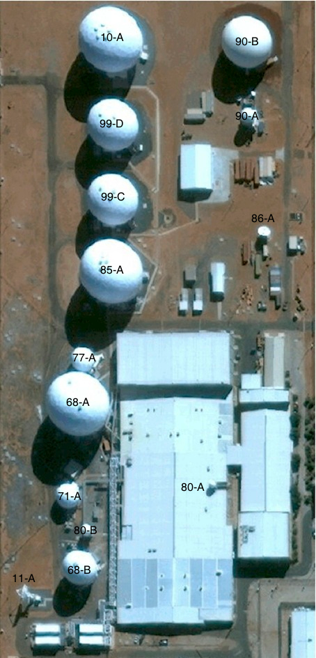
Figure 4. Principal SIGINT and FORNSAT/COMSAT parabolic antennas in radomes
(Antennas 90-A, 10-A, 99-D, 99-C, 85-A, 77-A, 68-A, 71-A, 68-B)

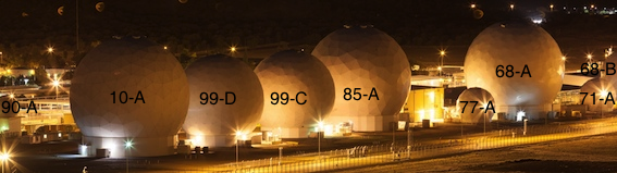
Source: Kristian Laemmle-Ruff, (Attribution – NonCommercial CC BY-NC).
—
The remainder of this Special Report is available in the full PDF version here [7 MB].
An online-optimized version for faster download here [ 2.6 MB].
—
III. References
[1] Duncan Campbell, ‘”Torus”: has one word in a Snowden leak revealed a huge expansion in surveillance?’, Wired.co.uk, 28 May 2015, at http://www.wired.co.uk/news/archive/2015-05/28/torus-duncan-campbell-report. On the Five Eyes Torus FORNSAT/COMSAT interception system see Desmond Ball, Duncan Campbell, Bill Robinson and Richard Tanter, Expanded Communications Satellite Surveillance and Intelligence Activities utilising Multi-beam Antenna Systems, Nautilus Institute Special Report, 28 May 2015, at https://nautilus.org/wp-content/uploads/2015/05/Torus-SATCOM.pdf.
[2] The existence of Antenna 01-C is implied in the May 2002 Ministerial Statement that three uncovered antennas were installed between the 1999 official photograph (Figure 31) and May 2002.
IV. Nautilus invites your responses
The Nautilus Peace and Security Network invites your responses to this report. Please send your response to: nautilus@nautilus.org.
The views expressed in this report do not necessarily reflect the official policy or position of the Nautilus Institute. Readers should note that Nautilus seeks a diversity of views and opinions on significant topics in order to identify common ground.
This base is essential for both the US and Australia.