
TOVUUDORJ PUREVJAV
SEPTEMBER 20, 2020
I. INTRODUCTION
In this Special Report, Tovuudorj Purevjav presents a description of the Mongolian electricity grids and their interconnections, a review of the present systems, technologies, and software for collection of grid data on the Mongolian electricity system, a description of existing methods for electricity demand forecasting in Mongolia, a summary of protocols for data exchange and data sharing currently in use in Mongolia, and plans for improvement of data gathering.
A summary of this report follows. A downloadable PDF file of the full report is here.
Tovuudorj Purevjav is Advisor, Green Energy International LLC.
This report was produced for the Regional Energy Security (RES) Project funded by the John D. and Catherine T. MacArthur Foundation and presented at the RES Working Group Meeting, Tuushin Best Western Premier Hotel, Ulaanbaatar, Mongolia, December 9-11, 2019.
The views expressed in this report do not necessarily reflect the official policy or position of the Nautilus Institute. Readers should note that Nautilus seeks a diversity of views and opinions on significant topics in order to identify common ground.
This report is published under a 4.0 International Creative Commons License the terms of which are found here.
Banner image: Schematic of the Mongolian grid system and its interconnections.
II. NAPSNET SPECIAL REPORT BY TOVUUDORJ PUREVJAV
MONGOLIAN GRID DATA TO BE SHARED IN DISCUSSIONS OF INTERNATIONAL ENERGY INFRASTRUCTURE
TOVUUDORJ PUREVJAV
SEPTEMBER 20, 2020
Summary
The development of power grid interconnections in North-East Asia will offer numerous benefits to the countries of the region, and will be one of the key elements in the building of a sustainable energy system in the region. Mongolia’s vast renewable energy resource will be a strong pillar for this development. The interconnected power system will require a flexible and efficient information and communications framework to ensure the collection of timely and accurate information from various locations in the interconnected power grids in order to support continuous and reliable operation of the interconnections. Thus, it is vital to assess the readiness of interconnection participants to provide information and determine the status of current grid data availability, data collection systems, and communication infrastructure. Although the Mongolian power system consists of five interconnected but mostly separate grid network, the Central Energy System (CES) is the largest and most complex system among them. The CES is monitored using supervisory control and data acquisition (SCADA) technology; recently, a WAMS (Wide Area Measurement System) technology has been deployed in the system. These systems collect essential parameters from various sensors, and the collected data are used for system analytics. Also, other systems such as an Advanced Meter Reading (AMR) system and a Dispatcher’s Online Information System (referred to as DisNews) are in active use by the CES system operator. This paper describes the current conditions of those collection systems, the development of communication infrastructure, data exchange requirements and the Mongolian government position on sharing of grid network data with interconnection partners. Next, it addresses the applications of grid data in Mongolia and discusses how forecasting techniques make use of the collected data. Finally, it proposes priority measures to be considered for the improvement of the data gathering process in Mongolia to ensure readiness for data sharing when the Mongolian grid is a part of interconnected regional power systems.
1 Introduction
1.1 Brief Summary of Mongolian Electricity Grids
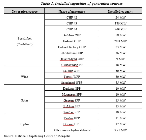
In Mongolia, electricity is almost entirely (82%) produced by a total of nine coal-fired power plants, with generation from renewable energy (13%) and from small diesel generating plants (5%, mostly in remote areas) providing the rest of the nation’s supplies. The total installed capacity of generation is currently (2019) 1476.6 MW consisting of the following generation sources: The total capacity of CHPs (combined heat and power plants) is 1162.2 MW
- The total capacity of Wind Power Plants is 155 MW
- The total capacity of Solar Power Plants is 60 MW
- The total capacity of Hydro Power Plants is 26.21 MW
- The total capacity of Diesel Power Plants is 72.6 MW
Table 1 provides a listing of the capacities of power plants in Mongolia by type.
In 2019, the total electricity consumption of Mongolia has reached almost 9 TWh (terawatt-hours). 81% of which was supplied by domestic generation sources and 19% of which was provided by power imports.
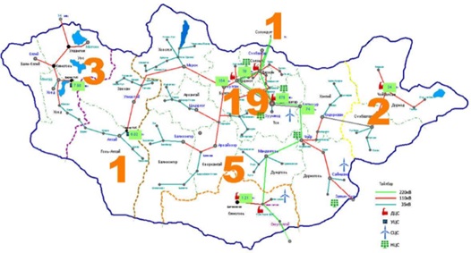
The Mongolian power grid consists of five systems (Figure 1). Table 2 shows electricity consumption and transfers in 2019 for each of the five systems.
- The Central Energy System (CES)
- The Western Energy System (WES)
- The Altai-Uliastai Energy System (AUES)
- The Eastern Energy System (EES)
- The Southern Energy System (SES)
Figure 1: The power systems of Mongolia
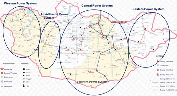
Source: Dispatching Central Department, National Dispatching Center of Mongolia
Table 2: Electricity consumptions and imports by power system in Mongolia, 2019
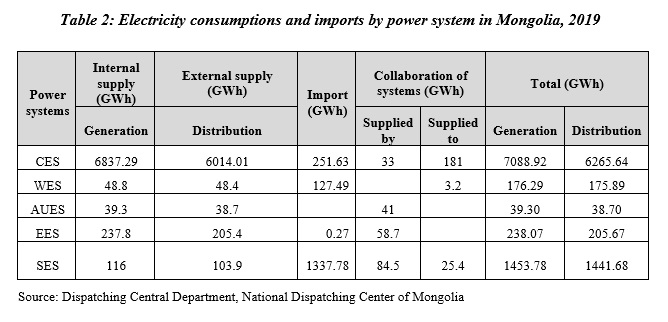
Source: Dispatching Central Department, National Dispatching Center of Mongolia
The CES supplies electricity to consumers in the central part of Mongolia, which covers more than 70% of the territory and 80% of the population of the country. The CES includes 6 coal-fired CHPs, 3 Wind power plants (PPs), and 5 Solar PP, and is connected to the Russian power grid by a double circuit 220 kV OHL (overhead line) to allow imports of electricity. The CES is also connected to the EES and AUES by 110 kV OHL, over which power is transferred to the CES from the other two systems.
The WES imports electricity from Russia via a 220 kV OHL. The Durgun Hydro Power plant, with a capacity of 12 MW, operates in parallel with the import line in this system and supplies electricity to the consumers in the three western provinces.
Operation of the AUES is based on the Taishir HPP with a capacity of 11 MW and diesel generators and imports of electricity from the CES in some areas. The AUES supplies power to consumers in the Govi-Altai and Zavkhan provinces. The EES operates based on a CHP plant with a capacity of 36 MW to supply electricity to consumers in Dornod and Sukhbaatar provinces and the Sukhbaatar branch of the EES is connected to the CES by a 110 kV OHL. The SES is connected to the CES by 110 kV and 220kV OHLs, and the Dalanzadgad CHP with a capacity of 9 MW is operated in parallel with these imports from the CES to provide electricity supplies for the SES.
The main load center in Mongolia is the central zone, which includes the City of Ulaanbaatar. The main transmission lines in the CES are 220 kV and span a total of 1,412 km between the Russian border and the following substations: Darkhan, Erdenet, Songino, CHP4 (in Ulaanbaatar), Ulaanbaatar, Baganuur, Choir, Mandalgovi, Tavantolgoi, and Oyutolgoi. The maximum voltage level of the existing system under current operation is 220 kV.
1.2 Brief Summary of Plans for Mongolian Grid Expansion/Reinforcement
The Mongolian government has an ambitious energy policy to address the power shortage issues in the country. In 2015, the Mongolian government published the State Policy on Energy document, setting out plans for the medium- and long-term goals for electricity sector development. State Policy on Energy 2015-2030 is a policy document describing the implementation of measures to improve the legal environment, optimize the organizational structure of the energy sector, improve the utilization of energy resources, develop fuel reserves, chart a course for development of electricity and heat generation and related supply activities, develop public-private partnerships to invest in the energy sector, transform the sector into a regulated competitive market, and develop the capabilities of the Mongolian personnel in the energy industry.
The policy document sets six different strategic goals for the Mongolian energy sector:
- Create an integrated energy system that is reliable and flexible with sufficient generating capacity reserves to serve domestic demand.
- Establish a fair long-term power export and import agreements with neigh-boring countries and implement the capability to export wind and solar power to countries of Northeast Asia on a large scale.
- Improve the quality of local training for engineers and technicians to match international standards, and develop an institution focused on energy economics, energy production, testing and calibration studies.
- Establish a regulated and competitive market for electricity where the tariff and pricing system is based on real costs to allow an appropriate profit level to ensure the financial soundness of the sector and encourage private investment in the sector.
- Utilize advanced technology in controlling and supervising energy generation, trans-mission, distribution and other supply activities, reduce electricity losses, and create a nationwide program to encourage the application of energy efficiency and savings measures.
- Reduce the adverse environmental impacts of conventional power generation through le-gal and tax measures, and by promoting renewable energy investments to increase the share of renewable energy in overall installed capacity to 20% in 2020 and 30% in 2030. Solar, wind, biomass, liquid and gaseous fuel, geothermal, fuel cell and other new sources and technologies should be utilized for power generation while creating a system where surplus energy can be supplied to the grid.
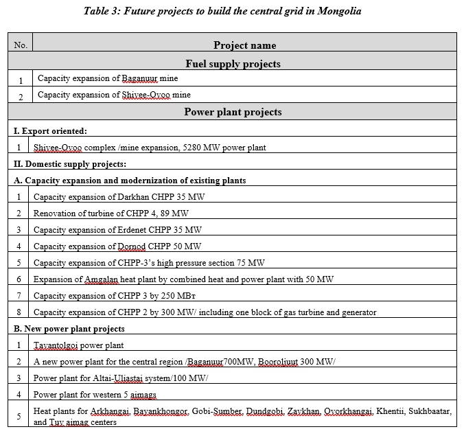
To meet the goals of the government policies described above, the main grid expansion projects included in Table 3 are described in the policy document.
The Mongolian electrical system is currently characterized by a significant dependence on neighboring countries, especially from Russia in the North and West and China in the South. Due to the current development of mines in the South region of Mongolia, a load demand forecast with a very sharp growth has been also presented for the 220 kV substations of Tavantolgoi and Oyutolgoi. Power supply to these substations (Tavantolgoi and Oyutolgoi) will be most likely provided through new OHLs from Ulanbaatar to Mandalgovi and on the Mandalgovi-Tavantolgoi-Oyutolgoi route, and by new power plants planned for the South Region.
1.3 Summary of Possible Regional Interconnections
North-East Asian (NEA) countries have significant potential for harnessing complementarities in energy resource endowment as well as in energy production and consumption. In particular, an interconnected power system across this large geographic region and multiple countries would provide more reliable and cleaner energy and help resolve problems related to intermittency of power generation from renewable sources, thereby supporting an energy transition and energy security in North-East Asia and contributing to combating air pollution and climate change. Mongolia’s renewable capacity expansion plan aims to develop a methodology to support Northeast Asia Power System interconnection planning to ensure the reliable delivery of renewable electricity, including from Mongolia, to load centers in NEA. Ultra-high voltage (UHV) transmission technologies are expected to be applied for the Asian interconnected system that will connect China, South Korea, Mongolia, Russia and Japan. As the Mongolia power market is small, it is not possible for renewable generation in significant amounts to be absorbed locally within the Mongol system. Therefore, renewable generation has to be exported to neighboring countries. Also, the North-East Asian Power Interconnection (NAPSI) is included in the goals of the State Policy on Energy 2015-2030, and several grid studies have been conducting and international conferences, forums held regarding on the topic of exporting Mongolian wind and solar power to the other countries in NEA.
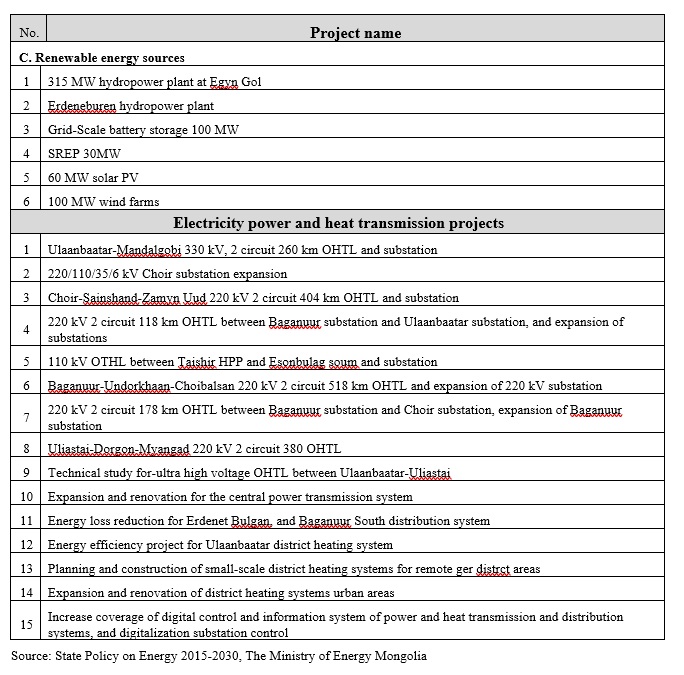
As the capacity of a future Mongolia – China interconnector is assumed to 2 GW, given the strong system provided by a UHV AC power grid, it is assumed that the connection point at China side of the Mongol – China interconnector could be connected to Ximeng, which is a key node on the eastern China UHV AC system, and is close to the major demand centers of Beijing and Tianjing. In addition, the area has good voltage support from nearby conventional power plants in China. The connection point is shown in Figure 2below. To interconnect with China and the Republic of Korea (ROK), it is assumed that the converter station at China side would be located in Wei Fang as shown in Figure 2, as it is a major UHV AC power grid node, and for an interconnector of 2 GW, no major reinforcement would be required if the line from Mongolia is connected at this site.
Figure 2: Illustrative diagram of North East Asia Interconnections
Source: The Ministry of Energy, Mongolia
At present, the Mongolia transmission system is already planned to be reinforced to integrate renewable generation, meet rising demand, and improve system reliability. Specifically, a new overhead line from Ulaanbaatar to Mandalgovi, at 220 kV, has been commissioned, and the transmission line infrastructure can be upgraded up to 330 kV. This development will provide a backbone for the system connection between Russia and China.
1.4 Map to Reminder of Paper
The paper is organized as follows: section 2 describes broadly the current status of grid data collection systems in Mongolia and how these systems are adapted to fit the needs of the power system; section 3 describes how forecasting techniques and data are used in planning; section 4 describes the existing protocols in Mongolia for data collection systems, and general practices for data sharing among electricity sector partners; section 5 discusses further actions for the development of data gathering; and section 6 offers conclusions related to the topic of this paper.
2 Mongolian Resources for Collecting Electricity Grid Data and Plans for Future Development
2.1 Existing Databases
Expanding and developing grid databases is becoming increasingly vital to support the process of modernizing the Mongolian energy sector. By connecting engineering applications with data collection systems, strong grid database systems will allow the identification of issues in the existing power system more accurately. Also, integrating grid databases to create “big data”, or a data warehouse, for the power system field is a still hot topic globally. The capability already exists in the Mongolian energy sector to integrate databases of grid-related information and introduce an open-source grid data platform (such as OpenEI, energydata.info, OpenGridMap, etc.), it is too early to discuss this type of initiative at this stage. In other words, a common or integrated information system of the energy sector has not been implemented in Mongolia as of yet, and all electrical utility companies have been managing their databases based on their own scopes of service of and operations.
For example, the power system operator, National Dispatching Center, has several databases to control and maintain the integrated power system of Mongolia. The majority of the databases maintained by the system operator have consisted of real-time and historical measurements of fundamental parameters from the grid.
These include:
- Supervisory Control and Data Acquisition System database:
- Real-time measurements of system parameters
- Historical measurements of system parameters
- Energy metering
- Substation facility status reports
- Alarm recordings
- Regime planning information
- Wide Area Monitoring System database:
- Real-time measurements of system parameters
- Historical measurements of system parameters
- Phasor measurement results
- Fault recording
- Advanced Metering Reading database
- Feeder and generation side measurements
- Asset information of connection points
- Power system settlement
- Dispatching Information System database
- Regime planning information
- News for utility dispatchers
- Report energy sector technological information
- Relay Protection and Post Fault Analysis database
- Relay protection and system automation operation report
- Post fault measurements
- Relay protection and system automation settings
In addition, some databases such as asset information and technical specification are being developed in the local environment (generation, transmission or distribution, etc.), and some utility companies select staff or engineers to collect parameters or measurement results for database updates. This method of manual data collection is still used in the Mongolian energy sector, though it obviously has drawbacks related to data validation. Although a few utilities have introduced new asset information systems to develop their asset databases, deployment of these type of information systems in the operational environment are still insufficient.
Database systems for power plants have different structures and contents depending on the type of energy source used for the plant. For example, a database system for a coal-based power plant records and processes data specific to coal-operated stream turbines such as main steam pressure, feed water temperature, reheater spray, flue gas temperature, excess air coefficient, and condenser vacuum. Also, some generation companies have asset information systems in which they store technical specification information or other crucial parameters for their infrastructure, configuration settings of equipment, and other data. Furthermore, each generation company has its own SCADA/HMI database and some utilities manage metering databases.
Transmission and distribution utility companies have similar databases. Generally, their technical asset information systems include information on transmission and distribution lines, substation facility equipment, technical specification data, and measurement databases. Also, some distribution utilities have been developing databases of geo-spatial information describing their assets by using ArcGIS software. Unfortunately, a GIS database of the transmission network is not yet fully developed. Mostly, the location coordinates of transmission lines are stored as hard copies of engineering drawing or collected in office programs such as Excel and AutoCAD. Distribution utilities also manage consumer information databases that have been developed through metering systems.
2.2 CADA Operations Data
The power system includes power generation, transmission and distribution assets that must be carefully monitored and controlled. Thus, the development level of SCADA (supervisory control and data acquisition) systems for those assets is needed and the process of collecting SCADA data requires a variety of hardware and software seamlessly integrated into a system that can perform monitoring and control operations for the large systems involved. The vital data to be collect by SCADA systems is determined based on the purpose of the SCADA application. For example, capturing continuous wind speed data with SCADA in wind farms enables the local operator to adjust the pitch controller of the wind blade to maintain optimal output by the wind turbine without risking damage to the turbine. These types of SCADA data applications are mostly at the local level where an industrial process needs to be controlled for power generation.
On the other hand, the integrated power grid of Mongolia is monitored remotely by the National Dispatching Center, and the following operational data are the main types of data collected with a SCADA system from the key nodes of the grid:
- Circuit breaker status
- Isolation switch status
- Grounding switch status
- Active and reactive power of overhead lines
- Transmission line currents
- Transformer active and reactive power
- Reactive power of reactors
- Frequency
- Substation bus voltages
- Energy meters
- Alarms of system violations
- Generator active and reactive power
- Ambient air temperatures
The current SCADA system used by the system operator in Mongolia encompasses 2370 double status points, 570 single status points, 1355 analog points, and 163 accumulators that are generated from 31 RTUs (remote terminal units) installed in the major substations.
To elaborate these RTU site locations specifically by energy system:
- The Central Energy System – 20 sites (including one in the Russian system)
- The Western Energy System – 3 sites
- The Altai-Uliastai Energy System – 1 site
- The Eastern Energy System – 2 sites
- The Southern Energy System – 5 sites
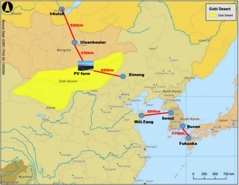
Figure 3 show a map of the locations of these data collection points in Mongolia.
Figure 3: Data collection points of the Mongolian SCADA system
Source: IT and Telecommunication Department, National Dispatching Center of Mongolia
These data are collected in the SCADA system and used for following the basic applications by the system operator:
- Basic data processing for data acquisition, data processing, distribution and storing in the operational database.
- Network control for testing (e.g. interlocks), executing and monitoring switching operations (individual operations and switching sequences)
- Free insertion of temporary jumpers, ground connections and isolating points on-line for temporary network modifications (without changing the source data)
- Switching procedure management as a supporting tool for creation, checking and executing switching procedures in the network (in-process and study mode)
- Selection control for operator guidance for alarms and deviations of the power supply network from the normal state
- Logs for recording alarms and indications (operation journals)
- Fault data acquisition for analyzing states in a power supply network before and after faults
- Topology analysis for interactive topological path tracing and network coloring depending on the current state of the network (e.g. grounding)
- Report generator as a tool for fast creation, management and output of reports (structure can be configured individually)
- Load shedding as a tool for defining and executing various emergency strategies (e.g. manual, rotating, on overload, etc.)
2.3 Data Collection Systems and Operations
Currently, there are three main data collection systems that are used for operation of the Mongolian grid. These systems are used by the system operator – the National Dispatching Center.
- SCADA system
- Wide Area Monitoring system
- Advanced Meter Reading system
2.3.1 SCADA system
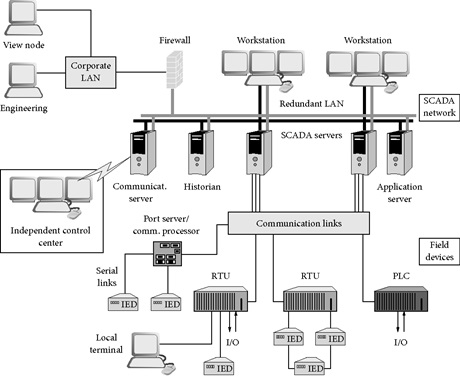
Generally, the current SCADA consists of four fundamental components (Figure 4). The system was established in 2006. The fundamental components are:
- Remote Terminal Units
- Communication Network
- Master Station
- User Interface or Human Machine Interface
Figure 4: Basic architecture of the SCADA system
Source: Dispatching Central Department, National Dispatching Center of Mongolia
- The Remote Terminal Unit (RTUs) are the eyes, ears, and hands of the SCADA system and are installed in the substations to collect data (analog, digital and pulse, etc.) from intelligent electronic devices, parallel inputs, and outputs, serially connected and communication systems. The collected data are sent to the master station in the National Dispatching Center via various network topologies. At the same time, the RTUs receive control commands from the master station and transmit these commands to the field devices, thus justifying the comparison to the “hands” of the master station. This kind of automatic operation, however, has not been implemented yet in the National Dispatching Center.
The RTU (see Figure 5) has the following major components to accomplish the tasks of monitoring and controlling the field devices:
- Communication Subsystems: Communication in the interface between the SCADA communication network and the RTU internal logic. This subsystem receives messages from the master, interprets the messages, and initiates actions with the RTU that in turn initiates some action for the completion of the task. The RTU also collects data from the field and processes and conveys relevant data to the master station.
- Logic Subsystem: The logic subsystem consists of the main processor and database and handles all major processing, timekeeping, and sensing for the control system. The logic subsystem also handles analog-to-digital conversions and computational optimization, in most cases.
- Termination System: The termination subsystem provides the interface between the RTUs and external equipment such as the communication lines, the primary sources, and substation devices. RTU logic systems need to be protected from the harsh environment of the substation.
- Power Supply Subsystem: The power supply for the RTU converts primary power, usually from the substation battery, to meet the supply requirements of the other RTU subsystems.
- Test/HMI Subsystem: This subsystem covers a variety of components, built-in hardware/firmware tests, and visual indicators within the RTU, and built-in or portable test/maintenance panels or displays.
Figure 5: Illustration of Remote Terminal Unit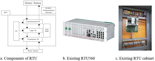
Source: Dispatching Central Department, National Dispatching Center of Mongolia
The data acquired in the RTU system mainly consists of analog and digital signals. Pulse data also are acquired, as per requirements, in case of miscount accumulation. The analog data involve all continuous, time-varying signals from the substations or generators. For example, the voltage transformers step down the voltage from the kilovolt level to 110V, and the voltage transducers convert physical signals to milliampere current (normally 4 to 20 mA) range which is then used for further transmission.
Currently, the Mongolian grid SCADA system’s connected sites are equipped with IME transducers to convert analog values to digital values. Digital signals are discontinuous signals that change from one state to another in discrete steps. Usually such signals are represented in binary, or two-level low and high. These signals include switch positions and isolators, and the circuit breaker positions of the substations. Digital signals can be directly accessed by the automation system; however, for physical isolation, all digital signals come into the system via interposing relays. Interposing relays initiate action in a circuit in response to some change in conditions in that circuit or some other circuit. Potential free contacts are used to bring the data from the breaker contact, as seen in Figure 6. The coupling is electromagnetic from the circuit breaker contacts to the RTU so that no physical wiring from the field reaches the control equipment. Also, the pulse data refers to the periodic information to be acquired from the substations. It captures the duration between the changes in the value of signals (energy data, etc.).
Figure 6: Status point data acquisition example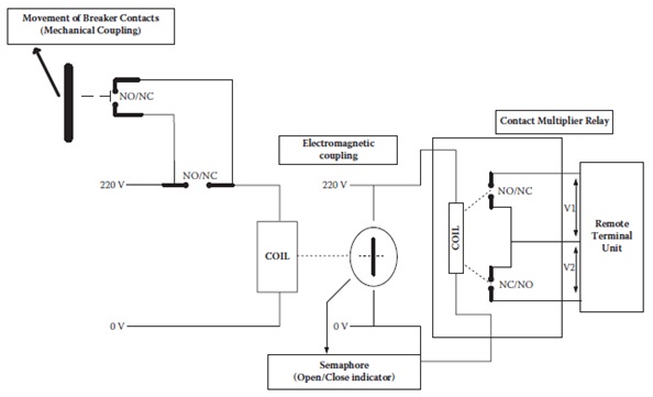
Source: Dispatching Central Department, National Dispatching Center of Mongolia
The RTUs collect and transmit a large number of data points (switch yard facilities, generators, CT and VT etc), and the scan time of each point is in the range of 2 to 10 seconds (for example, 2 seconds for digital values and 10 seconds for analog points), which gives an indication of how much data is received at the master station or at a higher point in the control hierarchy. Thus, most of the RTUs are configured for analysis of status point changes and report only the high-level action. For example, when a circuit breaker operates, numerous analog point alarms can be generated and the important message to provide the system operator is the fact that the circuit breaker operated (primary alarm), but the present system also provides the analog point alarms (secondary alarms). The objective is to log all the analog point changes in the master station for post-engineering analysis but report only the breaker operation to the system operator. Thus, intelligent data processing configurations must be implemented in RTUs. Also, due to the bandwidth capability of the communication system, some time-stamped data must be stored in the server of the master station, and its maximum time interval is 15 minutes.
- The second component is the communication system that carries the monitored data from the RTU to the control center and the control center commands from the master station to the RTU or data concentrator to be conveyed to the field. The communication system is the backbone of SCADA operation, and provides critical information that is time-bound to to the master station for use to control decisions to the field.
All RTUs support the standard protocols IEC-60870-5-101 and/or IEC-60870-5-104 to send data via communication networks. Also, RS485/RS232C communication interfaces and DNP3 protocols are acceptable to connect other devices such as transducers, HMIs, converters, etc.
The existing communication system that connects the existing population of RTUs to the current SCADA of the Mongolian National Dispatching Center encompasses:
- Redundant data and voice communication
- Line traps and coupling capacitors
- Digital Power Line Carrier (dPLC) for voice and data communications
- SDH/STM-1 fiber optics links
- Private Automatic Branch Exchange (PABX) at several substations
- Optical Ground Wire (OPGW)
- Underground fiber optic cables
- Optical Terminal Equipment
- Microwave links
- Telephone systems
There are three major communication techniques used to transport data within the Mongolian SCADA system (see Figure 7). These are:
- Optical Fiber Link
- Power Line Carrier
- Microwave
The reason for using these different communication network options is because of the remote locations of substations in Mongolia. In addition, the lack of independent communication networks or infrastructure for the power system controlled by the SCADA system still presents a problem for the Mongolian energy sector. Whereas education, telecommunications, and other state sectors have their own independent IT infrastructure, the SCADA system does not have entirely independent channels. Thus, some communications channels in the SCADA communication network are provided by third parties or carrier operator companies that provide channel renting services. These communication options are used for remote areas where SCADA-specific communication network options are insufficient.
Figure 7: The CES Network Configuration for existing SCADA system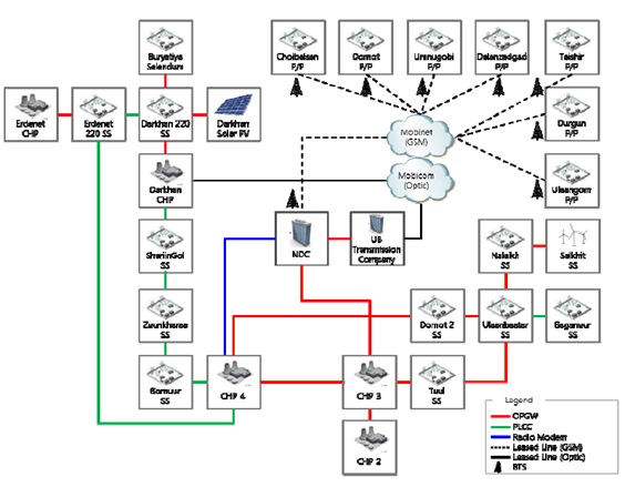
Source: Dispatching Central Department, National Dispatching Center of Mongolia
Also, due to the following two reasons major the system operator, the National Dispatching Center, adheres to the use of OPGW in its communication system:
- The extent of the power system, with large geographical regions extending to thousands of kilometers, implies that the communication system has to be robust, reliable, and physically feasible.
- The speed of data transfer required in a power system for critical data is in milliseconds, which makes it imperative to use technologies and protocols that aid in this aspect. A fast communication channel is essential for functions like phasor measurement unit (PMU) applications, automatic generation control, transient stability, and oscillation data, and for demand response mechanisms to work.
The CES transmission system consists of 220 kV and 110 kV overhead lines and includes 6 substations operating at 220 kV and 65 substations at 110 kV. Also, the 220 kV transmission system is connected to the Russian grid. The total length of the 220 kV transmission lines in the CES is about 1,412 km, and the length of the 110 kV lines is about 3,379 km. Optical fiber links using OPGW have been implemented for providing communication connectivity from 13 RTUs to the SCADA control center. OPGW has been installed on top of the 110 kV transmission tower network in Ulaanbaatar inside the Ring, up to the Salkhit wind park and near the Erdenet and Darkhan substations.
In addition, a PLC (power line carrier) communication system has been implemented for providing communication connectivity between the SCADA main system in Ulaanbaatar city and some of the RTUs located at sites a long distance from Ulaanbaatar. The main considerations for using PLC systems were low data requirement between the RTU and the SCADA master station, low cost, and extensive experience in Mongolia in the use of the PLCC system. Single-channel PLC communication equipment, where data transmission is superimposed over speech channel, is used. These systems, however, have limitations that include low capacity, low performance in long connections consisting of several hops, and limited frequencies. Moreover, PLC systems have the following shortcoming as a transmission media for modernized SCADA systems:
- Noise attenuation can be introduced through power lines
- Carrier frequencies are often not protected on a primary basis
- Inherently few channels are available
- Per-channel basis price is high
Furthermore, PLC communication systems have been operated for a very long period of time and are now outdated. It is thus necessary to replace and upgrade the existing outdated PLC communication system to produce a new system or to adopt another, better communication system. A microwave communication system was also implemented for connectivity between the system operator and the CHP-4 power plant to assist in meeting communication redundancy requirements. As the system requires clear “line-of-sight” for the design of the communication system, the antennas are mounted on high towers so that even trees and buildings cannot obstruct the path of the microwave signals. The microwave system, however, has the following shortcomings as the main transmission media for a modernized SCADA system;
- Frequency assignments require clearance from relevant authorities
- Spectrum scarcity
- Subject to interference due to line of sight technology (that is, the signal will not pass through objects) limits operating distances
- Microwave radio signals are affected by electromagnetic interference (EMI)
- Lower reliability than other options, as microwave radio communications are also affected by heavy moisture, snow, rain, and fog
- The third component of the SCADA system is the master stationwhere the operator monitors the power system and makes control decisions to be conveyed to the field. The SINAUT Spectrum (Figure 8) is defined as only q master station that physically exists in the system operator server room, and there are no sub-master stations that are implemented in designated substations or generators. In other words, the master station is a collection of computers, peripherals, and appropriate I/O systems that enable the system operator to monitor the state of the power system (or a process) and control it. A typical system would be hierarchical, with a single master and additional submasters, with each sub-master station reporting to the master station. The remote RTUs would typically be connected to the sub-master stations, but the current installed RTUs in Mongolia directly send operational data to the master station via the communication network.
Figure 8: SCADA internal system architect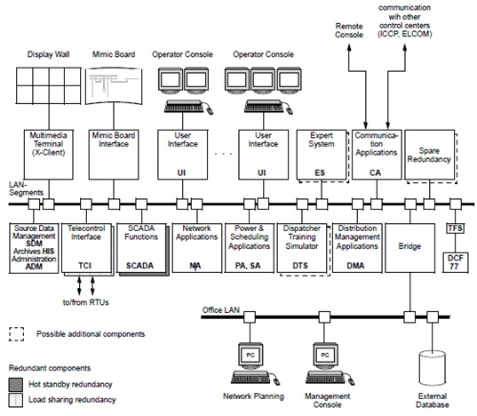
Source: Dispatching Central Department, National Dispatching Center of Mongolia
The current version of SINAUT Spectrum in the National Dispatch Center is 4.4 and it runs on the UNIX based operation system Solaris 8 (Figure 9). Based on the UNIX operating system, a real-time database and a relational database (ORACLE), these functions are used to organize data management, data exchange, and communication between the modules.
Figure 9: Illustration of SINAUT Spectrum
Source: Dispatching Central Department, National Dispatching Center of Mongolia
SINAUT Spectrum is an open, modular data and control system for electric power systems, and it contains a complete range of network control functions that includes the basic and user functions for SCADA. Also, it consists of self-contained subsystems or modules that intercommunicate via a defined interface, as shown in Figure 10.
Figure 10: The modules of SINAUT Spectrum are shown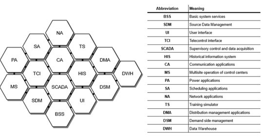
Source: Description of functions, SINAUT Spectrum, Siemens, 1998
The current SINAUT Spectrum system in use in Mongolia, however, has not been fully stacked with all modules, and at present it operates with following modules for which use is feasible to fill the system operator requirements under current conditions:
- SCADA
- Basic System Service
- User Interface
- Telecontrol Interface
- Source Data Management
- Historical Information System
- Power Applications
- Network Analysis
- Training Simulator
- The fourth component is the User Interface, also referred as to as the human-machine interface (HMI), which provides the means of interaction between the operator and the machine. The SINAUT Spectrum user interface (UI) brings the system operator closer to power system information by providing easy access to a wide variety of control system applications, as shown in Figure 11, Figure 12, and Figure 13.
Figure 11: User Interface of SINAUT Spectrum (Real time monitoring of CES)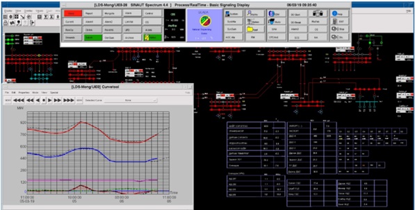
Source: Dispatching Central Department, National Dispatching Center of Mongolia
Figure 12: Daily load curve of the CES 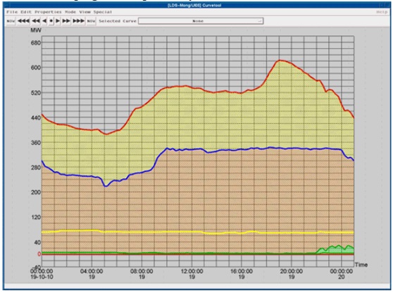
Source: Dispatching Central Department, National Dispatching Center of Mongolia
Figure 13: Power Generation Summary of CES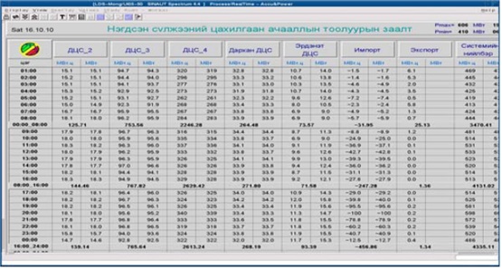
Source: Dispatching Central Department, National Dispatching Center of Mongolia
The main highlights of the SINAUT Spectrum UI can be summarized as follows:
- Graphic displays
- High resolution
- Multiwindow technique2
- Fast, direct mouse control
- Internationally standardized product design by using the OSF/Motif graphical user interface
- Fast display response time.
- Dynamic coloring of Network groups, grounded network parts, network parts with grounded faults, de-energized parts of the network, network islands.
- An open system
- Definable console access rights
- Interactive display construction
- Portable graphical user interface
- Relational Database Management System Data Access via operational data displays using UNIX scripts
Figure 14 shows the components of the SINAUT Spectrum UI system in use in the National Dispatch Center.
Figure 14: SINAUT Spectrum UI components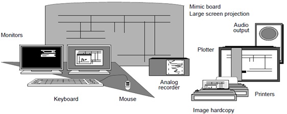
Source: Description of functions, SINAUT Spectrum, Siemens, 1998
2.3.2 Wide Area Monitoring System
The recent blackouts in the CES have raised serious questions about the reliability of the power system. Some of the recent major blackouts were the May 24th, 2015 and September 15th, 2018 events. The main reason identified for these blackouts was the increasing complexity of the modern power system that had driven it to operate under highly stressed conditions. These stressed conditions are due to the increasing demand for electricity, increasing machine size, long-distance power transmission, large seasonal load variations, environmental constraints, integration of renewable energy sources, and others. These stressed conditions, when their threshold limits are exceeded, may result in dynamic disturbances in the power system such as frequency deviation from nominal, large angular variations, etc. Real-time monitoring of power systems under these dynamic conditions is therefore very important to develop contingencies that enable operators to take remedial actions to avoid any potentially dangerous situations.
The reliable operation of the grid basically depends upon the situational awareness of the operators at different Load Dispatch Centers as provided by the data/information available to them in real-time. The stress on the grid can be represented by the angular separation of a coherent group of generators or between a pair of substations. With the conventional SCADA/EMS, it is not possible to measure or estimate the angular displacement in real-time. Therefore, a technology capable of measuring the magnitude and phase angle accurately to enhance situational awareness is an immediate need for the Mongolian EMS.
In this direction, a new technology known as synchrophasor technology is gaining momentum internationally and is really promising for the Mongolian energy sector. In 2019, the National Dispatching Center initiated a pilot project for WAMS implementation to test the technology in advance of large-scale deployment in Mongolia. The WAMS makes the whole system observable due to its ability to measure the voltage and phase angle accurately. Due to financial constraints PMUs (Phasor Measuring Units) cannot be installed on each bus, so have to date been deployed at strategically selected locations like generating stations, load center substations, interconnecting substations, etc. To make the system observable with PMUs at selected locations, state estimation is required to determine the voltage magnitude and phase angle for buses with no installed PMUs.
The current WAMS system covers the following major sites, and 24 PMUs have been deployed in the CES:
- Combined Heat and Power Plant #4
- Combined Heat and Power Plant #3
- Combined Heat and Power Plant #2
- Darkhan 220 kV substation
- Erdenet 220 kV substation
- Ulaanbaatar 220 kV substation
- Choir 220 kV substation
- Mandal 220 kV substation
- Dornot-2 110 kV substation
The telecommunication network used for the WAMS is mostly based on the OPGW communication system, and the standard protocols of the WAMS are IEEE C37.118, IEC 61850 and IEC 60870-104. These OPGW communication systems are a collaboration of several entities such as energy sector companies and communication network providers.
Figure 15: The basic architecture of WAMS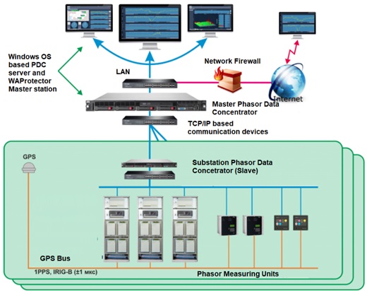
Source: http://energy.gov.mn/c/1059
The architecture of the system (Figure 15) is similar to the SCADA system, but instead of using Remote Terminal Units the system has equipped with Phasor Measuring Units (PMUs) that collect phasor measurements of electrical parameters from field devices. With the advent of PMUs, time-synchronized measurements are made possible on a real-time basis, which makes dynamic state estimation realizable. With the help of these estimates, transmission line power flows, proximity to operating limits, the optimal points of operation of generation and load, and other relevant information used by power system operators can be obtained. The PMU data not only help in the visualization of dynamic behavior and stability aspects of the power systems, but also help in pinpointing the location of events, which is extremely helpful in case of a blackout. Furthermore, these data are concentrated with Phasor Data Concentrators (PDC) and sent to the master station PDC where all analyses can be done with the available software applications.
The master station of the WAMS has the following capabilities:
- Basic monitoring and system supervision dynamic trend display, events, and alarms, single-line display
- Standard protocol PMU data links to exchange PMU data with other utilities, and to interface with SCADA/EMS systems
- Event-driven data archiving, monitoring of phase angle, line thermal, voltage stability, power oscillation, and damping
2.3.3 Advanced Meter Reading (AMR) System
AMR is a technology for automatically collecting data from electricity meters and transferring the data to a central database for billing and/or analysis. This means that billing can be based on actual consumption rather than on an estimate based on previous consumption, giving customers better control of their use of electric energy.
Traditional meter reading for electricity consumption and billing is done by human operators. This requires a lot of manpower and long working hours to achieve the data reading and billing of the complete area. Due to the increase in the development of residential and commercial buildings in Mongolia, labor and time requirements for metering have also increased, which in turn increases the operating cost.
Energy utility companies in Mongolia have developed AMR systems, and most of the distribution companies have introduced AMR systems in their operations. Due to financial constraints, however, no distribution company has to date fully installed smart meters (which is a fundamental device for AMR) for their customers. Furthermore, due to the non-existence of a smart code standard in Mongolia, the Mongolian energy sector has become crowded with a number of different type of smart meters, and as a result a data transfer problem still exists in the AMR systems of the utilities. AMR data communication technologies can be divided into two approaches, namely wired communication such as power line carrier (PLC) or telephone lines network (optical cable), and wireless communication such as radio frequency (RF), WiFi, ZigBee, GSM (Global System for Mobile Communications), General Packet Radio Service (GPRS), WiMax, and others.
In addition, the system operator, which is also the market operator, has an AMR system called Alpha Center. This system covers the CES and it is aimed to monitor common coupling points of generation, transmission, and distribution of electricity in the grid. The system collects data from approximately 1024 individual smart meters and 75 points are connected to the AMR system of the system operator (Figure 16).Many meters, however, are not compatible with the technical specification of the system, and have not been connected to the AMR system. The basic requirement for smart meters is the need to comply with the standards protocols IEC 1107, IEC 62056, IEC 870-5-102, ANSI, DLMS COSEM, and MODBUS.
Figure 16: Location information of the AMR system of the system operator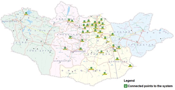
Source: IT and Telecommunication Department, National Dispatching Center of Mongolia
The communication network of the system operator’s AMR system is based on the GRPS network due to the need to include remote points and low service prices for GRPS (Figure 17). Also, metering data do not need to be obtained in real-time, and the minimum time interval of the data collecting process is 15 minutes.
Figure 17: The communication architecture of the system operator AMR system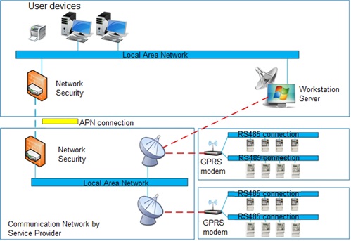
Source: IT and Telecommunication Department, National Dispatching Center of Mongolia
Some additional communication options are, however, still available for AMR communication network expansion in Mongolia. These include:
- Optical Fiber Link
- Power Line Carrier
- Public Switched Telephone Network
- GPRS Network by other system providers
2.4 Plans for Development of Data Collection Systems
In the Mongolian energy sector, with the deployment of the concept of smart grids and the increasing penetration of Information and Communication Technologies (ICT), digitalization is a reality. This digitalization can be seen in all steps of the energy value chain, from generation to distribution/retail. Thus, the next generation of the power system will be data-intensive, and the main databases need to be integrated to provide energy “big data” to inform advanced control and modeling functions. The application of big data techniques in power systems can lead to real-time optimization of power generation and transmission, accurate prediction of load demand and consumption patterns analysis leading to the provision of new services for consumers and distribution companies, and can allow the implementation of dynamic pricing strategies. Also, the database upgrading process is still underway in every level of the Mongolia electricity sector. These ongoing upgrades will provide a significant push for the development of database integration.
Furthermore, the National Dispatching Center is aiming to upgrade its current SCADA system to add additional EMS functionality. This plan will involve renewing its current workstation systems and other devices as well as implementing data exchanges that will be based on the OPGW communication system. In addition, the metering system of the system operator is being reviewed with an eye toward shifting the current system to a Metering Data Management System (MDM), in doing so there may be the possibility of integrating with distribution-level MDM systems. The benefits of this development including power system planning, system analysis, and control.
3 Existing Electricity Forecasting Systems in Use in Mongolia
3.1 Short-term forecasting
The system operator conducts planning in three stages, which are long (for one year), short (for one day) and medium (in between short and the long) planning for the Western Energy System, the Altai-Uliastai Energy System, the Eastern Energy System, and the Central Energy System.
Short-term forecasting focuses on predicting electrical hourly loads and energy demand for periods up to one week ahead considering that load demand is highly volatile on a day-to-day basis. Short-term forecasting is a very crucial element in the process of power system operational planning that affects the performance of many functions. Such functions include load flow studies, security and contingency analysis, economical dispatching, unit commitment, hydro-thermal coordination, preparation of preventive maintenance plans for the generators, transaction evaluation, reliability evaluation of the power system, and trading of power in interconnected systems.
The basic criteria for regime planning are:
- That they be based on technological procedures
- High reliability of schematics of the systems
- Consider the voltage level at system frequency and control
- Maintain feasible modes of operation
- Reflect the outside air temperature factor
- Reflect proposals of power producers
- Include economic aspects
- Consider of large investment projects in other major sectors (such as mining, construction, industry, national statistical committee, etc.)
- Include the capabilities of the core equipment and their maintenance schedules
- Reflect import and export agreements
- Compliance with the Energy Law, Renewable Energy Law, MOF, and the ERA regulations, resolutions and standards
The National Dispatching Center implements a daily regime of planning for the expected power consumption and production of the CES according to the procedure for evaluation and implementation of the Dispatching Graph Rule.
For regime planning, the expected consumption and consumption forecasts of the current period, the actual orders of the Transmission company for the central and other regions, and the actual distribution of electricity distribution networks, multi-year surveys, quarterly and meteorological data are considered according to the Unified Network Rule. Furthermore, the system operator provides a daily regime for participating generation utilities such as Coal-heated Thermal Power Plants, Renewable Power Plants, and other regional Power Plants based on the readiness of equipment and capacity availability, proposals from the plants, and the approved production plan for the year. Also, the National Dispatching Center continuously adjusts the balance of production and consumption between producers connected to the grid and adjusts the production regime based on certain pre-delivery orders from the producers.
NDC adjusts the daily regime of the grid to ensure that the consumers have the lowest cost of electricity and to reflect the government’s renewable energy policy. Daily monitoring of the implementation of the regime is assessed based on each deviation of the graphs of power plants’ output and performance and the deviations from plans and forecasts as affected by market relations rules.
Basically, the following formula is applied for the system operator planning.
E = α0 + α1 * r + ζ (t) + η
Where,
α0 – the base value of the electricity consumption
α1 * r – the trend of increase and decrease of consumption
r – 1, 2 …. time
ζ (t) – seasonal factor
η – mathematical disperse, random measurements
(The relative estimate error averages 9%. This is based largely on the errors in approximating seasonal and annual data.)
In addition, the following estimation methods are considered for the planning process:
- Average growth method
- Macroeconomic method
- Ambient temperature factoring method
- Power producers price comparing method
Figure 18 shows typical outputs of the one-day forecasting models in terms of production by power plant in Mongolia.
Figure 18: Daily regime given by the system operator
Source: Dispatching Central Department, National Dispatching Center of Mongolia
3.2 Medium-term Forecasting
Medium-term forecasting is used by power companies for maintenance planning. The forecast period is from several weeks to 12 months ahead. This type of forecast depends mainly on growth factors, that is, factors that influence demand such as large events, the addition of new loads, demand patterns of large facilities, and maintenance requirements of large consumers. This type of forecast is not concerned with hourly loads as are short-term forecasts but rather predict peak loads for comings days or for the weeks ahead. With this information, it can be decided whether to take certain facilities/plants off line for maintenance or not during a given period. The methods used for this type of forecast are similar to those used for the short-term forecast except that there is less need for accuracy. Also, the system operator forecasts for only one year. Usually, a one-year plan includes every participants’ interests, and the planning needs to be approved by the Ministry Energy.
3.3 Long-term Forecasting
As the name implies long-term forecasting is used to plan the expansion of the power system, that is what types of generation plants or transmission infrastructure are needed, and when, where, and in what size they should be deployed. Usually, generation system planning is done separately from transmission system planning. The study period for this forecast is from 1 year to 15-20 years ahead. The outputs of this forecast are usually the peak loads and annual energy requirements of the system. That is to say, the peak loads and energy requirements for the coming years of the study period are determined by using the forecasting method. Usually econometric or regression analysis methods are widely used in this type of forecast. End-use and expert system methods, however, are also used.
Unfortunately, long-term planning is not carried out by the National Dispatching Center. The long-term planning of electricity grid and expansions are determined by the Ministry of Energy.
4 Mongolia’s Existing Protocols for Data Exchange
The Mongolian grid data-sharing process is mostly regulated with the national grid code, which is in the process of upgraded by the system operator. When a new power source or any other power system facility is integrated with the grid, the system operator determines the technical requirements or connection protocols for that integration. If the capabilities of some operating systems are do not meet the system operator’s requirements, those requirements are met using other communication options such as using internet-based web browser applications to access to the local HMI or SCADA data from the substations or generators using the internet communications network.
The current protocols that are being used for the main systems in use by the system operator are shown below:
- SCADA: IEC-60870-5-101 and/or IEC-60870-5-104
- Advanced Metering Reading System: IEC-62056, DLMS, COSEM
- WAMS: IEC-60870-5-104 and/or IEEE C37.118.2
4.1 Data Sharing for Existing Interconnections
Furthermore, the National Dispatching Center is responsible for providing system operation information through the web-based dispatching online information system (Figure 19). Although the system itself is not as advanced as other energy system data exchange platforms like ENTSO-E’s Data Exchange Platform, which is used for European power system interconnection, it is the only available information platform for the operation of the CES. This system is integrated with the SCADA system, and most of the information is provided by the transmission system dispatchers to the system operator. Unfortunately, some data must be input manually by the dispatchers due to technical issues in the substations. In other words, the database of dispatching information systems is not fully configured to gather data from all major substations or from connection points where intelligent electronic devices have not yet been installed due to the financial constraints. Thus manual methods are used in which the system operator contacts the generation company and transmission company dispatchers through a communication network and requests information from the local installation. This method needs to be automated and integrated with the dispatching information system.
Figure 19: DisNEWS (dispatching online information system)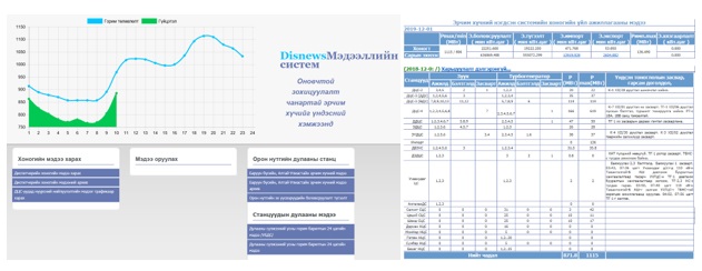
Source: IT and Telecommunication Department, National Dispatching Center of Mongolia
In addition, the energy utilities operating in Mongolia are typically hesitant to be totally transparent with their competitors, since they might lose their competitive advantage. Thus, GENCOs, TRANSCO, and DISCOs typically share just a subset of their grid data based on mutual agreements, to help improve real-time grid operations.
Data transfer solutions between energy entities are different in different instances and are based on the state of data. For example, sharing real-time data through monitoring systems requires management in operational databases and configuration of and agreement on data exchange protocols. Moreover, if the system or communication configuration of one or more parties exchanging is/are not appropriate for exchange, technical solutions must be considered between the parties such as installing a protocol converter in the communication system. Also, some data sharing processes in real-time monitoring involve providing web application-based user accesses. Some renewable plants provide user access to the system operator for monitoring the real-time operational status of their generation assets or metrological data in instances where the generator is not capable of connecting to the system operator’s SCADA system due to different vendor products or other technical constraints.
4.2 Existing Agreements for Data Sharing with Other Nations for Planned Interconnections
The CES is connected to the Russian system, which provides an ancillary service for operation of the CES system, and the data exchanges between the Russian and Mongolian system operators are crucial to maintaining the power systems. Operational parameters such as frequency, measurements of the voltage at the connection point and on the transmission line, and measurements of active and reactive injections or flows are mandatory for exchange, and data exchange confidentiality is ensured by an agreement between the Mongolia and Russian system operators. However, some grid information such as the nationwide grid topology, communication network access points, input values of relay protection, and automation system of the grid are still confidential due to considerations of National Security.
Operational grid data are exchanged using the IEC-60870-5-104 protocol between the Mongolian system operator and the Russian system operator. If the Mongolian power system is interconnected with other regional power systems such as Asian Super Grid, the current communication protocol will not be suited to the requirements of communicating between control centers. Thus, ICCP (inter control center protocol) is a more appropriate solution for regional control centers data exchanges. ICCP is based on client/server principles. The basic operation of this data transfer principle is that data can be requested from a control center (client) to another control center (server). Also, the exchange of non-operational data between control centers can be rectified with the Common Information Model, which supports implementing a power system data warehouse for the grid participants. Thus, if this data exchange system or its infrastructure is being developed, then the data-sharing agreements or contracts can be introduced for the grid participants.
4.3 Future Plans and Existing National Policies for Data Exchanges
Recently, in 2019, the Ministry of Energy and National Dispatching Center published a policy document for the information technology of the power system. The policy determines three major strategic plans for the next five years:
- The state central administrative body responsible for the energy sector is to establish an information technology system and structure, in order to develop rules set policies for data exchanges
- To develop an IT system that enhances the fairness, transparency, and productivity of the industry and the electricity companies’ operations and promotes their performance
- To investigate advanced technologies and introduce new products into the energy sector
Also, some critical points have been addressed in the policy document regarding the data exchange topic, as summarized in the points shown below:
- To develop and implement a nationwide Energy Management System for the Energy Sector
- To establish an energy information center or data center for the Energy Sector
- To create a data exchange platform for the Energy Sector
- To upgrade data exchange infrastructure and expande the connection points of the SCADA system
- To improve energy sector databases and implement a data warehouse for the Energy Sector
In addition, there are several locations in Mongolia that are highly isolated from the integrated power systems and where existing transmission lines have not yet been equipped with high-speed optical fiber to exchange grid data. Another objective of the development outlined above is to have an independent communication network only for use in Energy Sector data exchanges, especially for real-time monitoring and for controlling the power system. Furthermore, the grid data exchange policy for interconnection with other countries should be considered carefully as an input to the future development of the Asian super grid. This is in addition to the need for a grid data exchange platform for the use of the Mongolian energy sector itself to enable better power system research and data analysis.
5 Plans for Grid Development to Improve Data Gathering and Processing in Mongolia
Global electrical power grids are evolving into more intelligent, more responsive, more efficient, and more environmentally-friendly systems, often referred to as the smart grid. Smart grid operation is exclusively data-oriented, and the presence of intelligent data collection systems is mandatory. Given the current condition of data collection systems, however, the readiness of infrastructure and of information communications technologies, as well as the application of grid data analytics, are not yet adequate for assembling a smart grid in Mongolia. Therefore, the following key recommendations should be prioritized for the development of data gathering and data processing in Mongolia.
- Renew the current SCADA system or upgrade to EMS:
The current SCADA system, in Mongolia, SINAUT Spectrum 4.4 was established in 2006, and the version currently existing at the NDC cannot be incrementally upgraded. It must be fully replaced with a brand-new system built around the new processors and operating systems that dominate the SCADA/EMS industry today and, most probably, will continue to do so in the foreseeable future. The SINAUT Spectrum 4 platform was discontinued by Siemens in 2014, and like all of the other major providers of Utility Information Systems, Siemens has also recognized the obsolescence of the SPARC/Solaris platform and, in 2014, introduced the SINAUT Spectrum 7 SCADA/EMS product line, which is built around Intel 64 bit x86 servers and runs under the Redhat 64-bit Linux and Windows 64bit operating systems. Due to this change, it has become impossible to upgrade the current system platform and the server workstation, the SUN V240, is now no longer produced. The production of spare parts for the SUN V240 system has also been discontinued. Since then, the T5120, M3000, and T4-1 server types were produced, but now only the T4-1 server is produced. Therefore, to ensure the reliable operation of system operation a server upgrade is urgently needed. In addition, although there are several functions for power system control such as Power Application and Network Application on the SINAUT Spectrum, there is a currently a lack of usage of these functions in daily dispatching operations in Mongolia. This is due to the system version being relatively old and the availability of support services for the current software configuration is will be terminated soon. Full operation of the Energy Management System will require Automatic Generation Control, which will need to be configured in GENCO assets, and some of the main generators on the grid need to be equipped with Automatic Generation Controllers in order to allow fully optimal operation with the EMS. Also, the EMS will need to support expansion functions for distribution applications over the EMS operational system.
- To increase quantities of RTU and PMU devices in the system:
The existing RTUs on the Mongolian grid system, which were installed in the mid-2000s, comply with the existing RTU communication protocols standards. Therefore, only the installation of new RTUs will be contemplated in the following, although, depending upon the situation in the field, the upgrade of some of the existing RTUs to deploy state-of-the-art RTU technology may eventually have to be envisioned. Also, the Mongolian grid operator’s SCADA-connected sites are relatively few, and less than 50% of all substations are telemetered today. Thus, the RTU population needs to be increased to pave the way for implementation of smart grid infrastructure in the near future. Furthermore, the current WAMS system covers only 10 major high voltage points, and thus the use of PMU devices should be extended for future grid expansion. Adding collection devices will be a strong investment for power system analytics and will improve the prevention techniques to deal with any sudden disturbances in the grid.
- To extend the telecommunication network of the data collection system:
The National Power Grid of Mongolia is divided into five regions, and needs to provide efficient Energy Management in real-time in each of the regions. This can be achieved only with on-line data collection and processing. Thus, an intelligent SCADA system along with high-speed telecommunication facilities at every state becomes the strongest need for the central Energy Management system. To handle the large data flows that will be produced with the adoption of RTU, IED and IT-based SCADA/EMS components for the power system in Mongolia will requires a switchover to advanced telecommunication technology such as an optical fiber communication systems. The use of fiber optic-based communications offers the availability of phenomenal bandwidth. Not only this, but it also offers low attenuation and is capable of covering long distances with higher transmission rates, and also will provide a critical parameter in that it would be able to minimize data packet loss, which can deteriorate the estimation accuracy for time-critical faults in the grid. Currently, the OPGW of single-mode fiber type has been used to transfer the status of various data measurement and protection control signals and other parameters to the SCADA system. Such OPGW makes use of an optical signal of 1,310 to 1,550 nm wavelength in 6∼144 fiber cores. OPGW is a composite type of cable, used for the construction of electric power transmission and distribution lines. Such cable performs two functions; it provides a ground wire and also a communication link for the transmission of voice, video, and data by incorporating optical fibers within power cable. OPGW fiber cables will be used to replace conventional ground wire in old power lines with a resulting increase in communication capacity due to the addition of optical fiber. Overhead optical fiber systems will be able to play a key role in telecommunication facilities for the power sector network. In addition, these systems offer a distinct advantage in that no civil works are required for their installation. They can be installed along existing power transmission lines immediately. Thus, it is possible to minimize costs and most importantly, the time required to begin network operation. Existing and future data communication protocols should be modified/designed taking into consideration the characteristics of the power systems. If regional control centers are implemented in the Mongolian energy systems (except CES) then the ICCP (Inter-Control Center Communications Protocol)/ IEC-60870-6 will be used through the communication system. Another significant challenge is to ensure secure communication that is resilient to cyber and physical attacks.
- To expand advanced metering infrastructure and improve their application in power system analytics:
Utility companies have developed advanced metering systems for their own use, and these systems can be developed with communication networks and capabilities for integration of other systems in order to build advanced metering infrastructure (AMI). Some Mongolian utilities have initiated this type of project for their business. The AMI provides a two-way communication architecture between the smart meter and a utility company. The smart meter is an advanced meter that provides more detailed and accurate power consumption information than that of a conventional meter, and this information can be used for monitoring and billing purposes. Further, the AMI includes of local data aggregator units (DAUs) to collect and relay the information from the meter side to meter data management systems (MDMS), and also provides an active user interface to provide information access to consumers. The MDMS provides storage, management, and processing of collected data for proper usage by other power system applications and services. In other words, data about consumer behavior can be stored in MDMS, which can contribute to power system analysis and forecasting more effectively. Once the AMI is advanced, it can be integrated with other systems such as SCADA and WAMS, which will then provide strong input to processes for power system optimization. Also, AMI systems offer the possibility to implement demand response programs and to provide for consumer involvement in energy market operations, functions that will be extended eventually in the future
5.1 Potential Priorities for additional data collection devices
As previously mentioned, the use of data collection devices such as RTU, PMU, and IED across transmission substations shall be increased. Some of the remote area substations are still not connected to the SCADA system. Although the population of data collection devices on the Mongolian system grows annually, but the growth remains slow. One of the key factors for this lack of development is strongly related to availability of investment funds. Furthermore, IED for relay protection and fault analysis shall be considered as well. Unfortunately, there are still mechanical relay protection devices and analog measurement equipment in the system. Thus, renovating the aging infrastructure should be prioritized too. In addition, since the conventional grid is being transformed to the smart grid, data collection systems in distribution networks will need to be developed extensively, and smart devices such as smart meters and data concentrators should be installed on consumer premises and at feeder points. Once the smart meters join the AMI, a meter-reading collection process is performed. With the meter data, a management message distribution process can be used to help in adjusting electric power generation, transmission, and distribution accordingly.
5.2 Potential Priorities for upgrading data analysis and control facilities
In order to improve data analysis, the collection systems need to perform accurately. Unfortunately, the current SCADA system functions for power system analysis are not fully qualified due to technical issues. Thus, the system has to be replaced with another SCADA or EMS for better data analysis.
Another priority for data analysis is that energy system “big data” and data warehousing projects must be initiated in the Mongolian energy sector. The potential of constructing a “big data” source is seen as possible since there are a variety of data collection systems currently existing. The biggest concern is that data acquisition from utilities will be a challenge, and a possible approach is to solve this problem is active engagement of utilities by energy authorities regarding this foreseen problem.
The utilization of big data techniques can improve grid sustainability and reliability. Also, the life span of assets can be increased by providing a new vision related to operation and maintenance activities for electrical utilities. There are a large set of data sources to assist with providing this vision, which can be separated into different categories:
- Data from smart meters, through the deployment of advanced metering infrastructures (AMI)
- Grid assets data (primary equipment sensors)
- Third-party data (off-grid data sets) and asset management data (smart devices in the grid).
Because these data sources have very different natures, data integration/correlation becomes a core step of the value chain of the data-driven power system. By dealing with a huge amount of data from the electricity network, the meteorological information system, geographical information systems, etc., many benefits can be brought to the existing power system and can improve customer service as well as social welfare in the era of big data for energy systems.
5.3 Potential Priorities for Development of Human Capacity for Grid Control
Due to the rapid development of engineering technology, engineers who work in the energy sector must be have their knowledge updated constantly. Since the modern grid is becoming data-driven, engineers have to be qualified for data analysis. One of the current issues in the Mongolian power sector is that IT-based electrical engineers are in relatively short supply; by one study, there are approximately 60 IT engineers currently employed in the sector. This can be a drawback for ICT development in the energy sector. Thus, a policy of capacity building in the energy sector should aim to train employees for ICT technology advancement. Because the global power system advancement is collaborating with IT-based technologies such as the Internet of Things, machine learning, big data, etc., capacity-building for IT-based electrical engineers is particularly crucial. In addition, dispatchers of the power system should be prepared on dispatcher training simulators (DTS). The usage of current DTS at the National Dispatching Center is passive due to the technical issues. Thus, the DTS at the Center should be upgraded to allow for thorough training of dispatchers to carry out their duties in controlling the power system. Furthermore, the energy authority, the Ministry of Energy, has been cooperating with the Asian Development Bank and the World Bank on training of employees in the Mongolian energy sectors.
6 Conclusion
In this paper, the current development of grid data collection systems in Mongolia has been reviewed in detail, and potential further actions to develop data collection capabilities have been discussed. This review has included information regarding collection systems, communication networks, sector policy, and so on. The current SCADA system in use in Mongolia is diagnosed as having several technical issues, and the limited application of power system functions has been identified due to the lack of an upgrade to the system during the last decade. The system has to be replaced with a more advanced system to ensure EMS operation. In addition, the necessity of expanding the number of collection devices on the system for both SCADA and AMR applications are seen as needed. Advancements in data collection systems will be explicitly beneficial for use in data analytics and big data development. Moreover, expanding the current communications backbone with a high speed, topologically redundant fiber optics communications network would allow new SCADA and WAMS infrastructure to reliably and uninterruptedly communicate with the entire population of data collection devices in the transmission network, power plants, and substations. Implementing these recommendations will greatly enhance the development of a smart grid of Mongolia.
7 References
- The Ministry of Energy Mongolia, “State Policy on Energy 2015-2030”, 2015, available at: http://energy.gov.mn/laws/show/id/202
- World Bank, “Final Report: SCADA Diagnosis and Upgrade Concept Preparation”, November 3rd, 2017
- Asian Development Bank, “Strategy for Northeast Asia Power System Interconnection”, June, 2017
- Madrigal, M., Uluski, R. & Gaba,K., “Practical Guidance for Defining a Smart Grid Modernization Strategy”, World Bank, 2017
- Zhang, Y., Huang, T. & Bompard, “Big data analytics in smart grids: a review”, Energy Inform, 2018, available at: https://doi.org/10.1186/s42162-018-0007-5
- Tu, C., He, X. & Shuai, Z, et al, “Big data issues in smart grid – A review”, Renewable and Sustainable Energy Reviews, 2017, available at: https://doi.org/10.1016/j.rser.2017.05.134
- Thomas, M & McDonald, J, “Power System SCADA and Smart Grids”, CRC Press, 1st edition, 2015
- National Dispatching Center, “Information Technology Policy in the Energy Sector”, 2019, available at: https://ndc.energy.mn/?p=2243
III. NAUTILUS INVITES YOUR RESPONSE
The Nautilus Asia Peace and Security Network invites your responses to this report. Please send responses to: nautilus@nautilus.org. Responses will be considered for redistribution to the network only if they include the author’s name, affiliation, and explicit consent.